
A load-bearing plane conveying device

A conveying device and plane technology, applied in the direction of conveyor, transportation and packaging, can solve the problems of inability to achieve plane load-bearing conveying, increase the friction of the conveyor belt, increase the load of the transmission motor, etc., so as to improve the practical value and improve the production. Efficiency, the effect of reducing the coefficient of friction

Inactive Publication Date: 2011-11-30
郝钰 +1
View PDF0 Cites 3 Cited by
  • Summary
  • Abstract
  • Description
  • Claims
  • Application Information

AI Technical Summary

Problems solved by technology

[0002] The current conveyor belts for transporting materials on a plane are generally not load-bearing, and most of the conveyor belts for transporting heavier materials are not flat, let alone used as workbenches in the production line
Since the load-bearing conveyor belt is all under the conveyor belt, the friction between the conveyor belt and the pallet is increased due to the load-bearing, which will cause heat and wear, and increase the load on the drive motor, so it cannot be used for plane load-bearing conveying, and it cannot work as a production line. The table is used, because the workbench must not only bear weight but also withstand various requirements in the weight and production process, such as impact force and other loads
Therefore, there is no plane conveying device that can bear weight and be used as a workbench.

Method used


Image

  • A load-bearing plane conveying device
  • A load-bearing plane conveying device
  • A load-bearing plane conveying device

Examples


Embodiment Construction

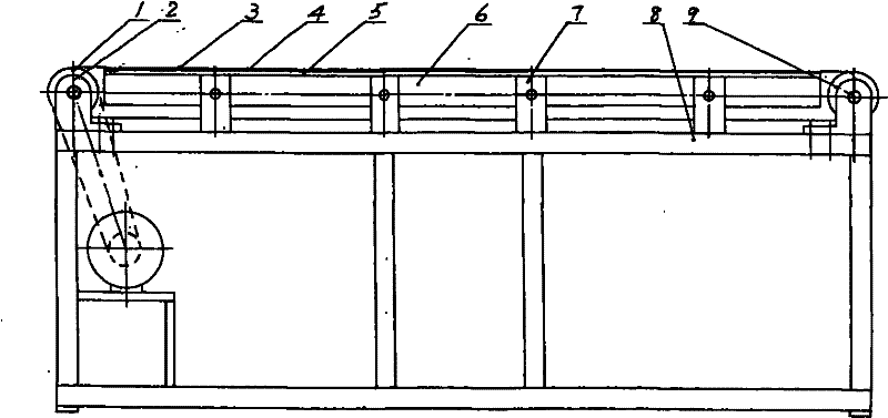
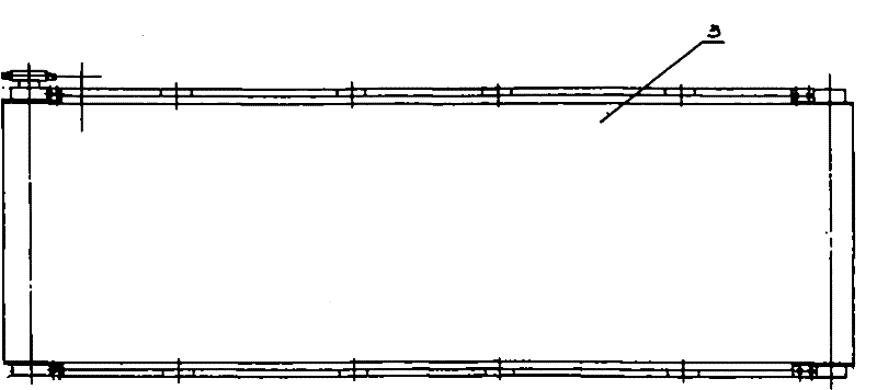
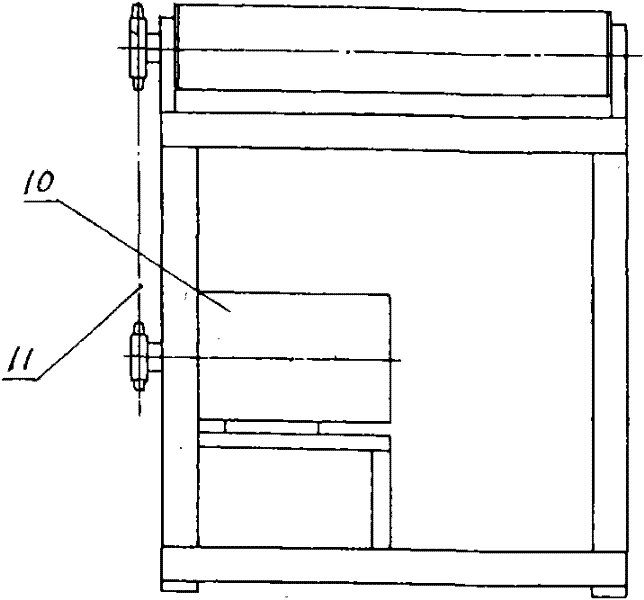
[0010] See attached figure 1 ~ attached Figure 4 Shown:

[0011] This embodiment is composed of driving roller 1, bearing seat 2, conveyor belt 3, graphite gasket 4, pallet 5, bracket 6, bracket 7, frame 8, driven roller 9, reduction motor 10, and transmission chain 11. The driving roller 1 is supported by the bearing seat 2 and installed on the left side of the frame 8, the driven roller 9 is supported by the bearing seat 2 and installed on the right side of the frame 8, and the geared motor installed in the middle of the left side of the frame 8 10 drives the driving roller 1 to rotate through the transmission chain 11, and the driven roller 9 rotates synchronously with the conveyor belt 3. The bracket 6 made of steel pipe is held flat, and the bracket 6 is installed on the frame 8 through the bracket 7, so that the bracket 6, the supporting plate 5, and the graphite gasket 4 are all installed inside the conveyor belt 3, so that the conveyor belt 3 can move in a plane an...


PUM


Abstract

The invention discloses a load-bearing plane conveying device, which is composed of driving rollers, bearing seats, conveyor belts, graphite gaskets, pallets, brackets, brackets, racks, driven rollers, reduction motors and transmission chains , the driving roller is installed on the left side of the frame, the driven roller is installed on the right side of the frame, the geared motor installed in the middle of the left side of the frame drives the driving roller and the conveyor belt forward through the transmission chain, and the graphite gasket under the conveyor belt , the supporting plate and the bracket are connected together, the graphite gasket is supported by the supporting plate, and the bracket is installed on the frame through the bracket. The present invention designs the load-bearing structure according to the lubricating characteristics, horizontal heat conduction characteristics and transfer characteristics of graphite. The graphite gasket supports the conveyor belt for load-bearing and plays a lubricating role in the relative friction movement. Due to the transfer characteristics of graphite, the graphite will move from The graphite gasket is transferred to the conveyor belt to achieve self-lubrication and reduce the friction coefficient.

Description

Technical field: [0001] The invention relates to the technical field of continuous conveying of materials, in particular to a conveying device in the form of a load-bearing plane conveyor belt, which can also be used as a load-bearing plane conveying device for a workbench of a production line. Background technique: [0002] The current conveyor belts for transporting materials on a plane are generally not load-bearing, and most of the conveyor belts for transporting heavier materials are not flat, and cannot be used as workbenches in the production line. Since the load-bearing conveyor belt is all under the conveyor belt, the friction between the conveyor belt and the pallet is increased due to the load-bearing, which will cause heat and wear, and increase the load on the drive motor, so it cannot be used for plane load-bearing conveying, and it cannot work as a production line. The table is used, because the workbench must not only bear the load but also withstand various ...

Claims


Application Information

Patent Timeline
Patent Type & Authority Applications(China)
IPC IPC(8): B65G15/30
Inventor 郝钰文静
Owner 郝钰
Learn More