Spacer structure for cross rollers

a cross-rolling, spacer technology, applied in mechanical equipment, transportation and packaging, moving seats, etc., can solve the problems of affecting operation, still some problems to be solved, and consumers still need uninterrupted technology improvement, so as to reduce friction waste

Active Publication Date: 2008-10-21
HIWIN TECH
View PDF8 Cites 9 Cited by
  • Summary
  • Abstract
  • Description
  • Claims
  • Application Information

AI Technical Summary

Benefits of technology

[0016]The primary objective of the present invention is to provide a spacer structure for cross rollers that can effectively reduce the friction waste.
[0017]The spacer comprises a frame and four protruding wings, the protruding wings are arranged in pairs on opposing sides of the frame and outwardly extend therefrom. The two inactive end surfaces of the roller are confined between the paired protruding wings of the spacer, so that the rolling surface of the roller will be free of surface-friction, effectively ensuring a smooth operation of the roller.
[0018]The secondary objective of the present invention is to provide a spacer structure for cross rollers that is more stable in the cross rolling direction.
[0019]The spacer is formed at two end surfaces thereof with protruding wings for positioning the roller, and the slenderness ratio of the roller is designed to be 0.7-0.98 for facilitating installation of the roller. Such arrangements ensure that the roller can move smoothly, and the protruding wings can provide a stable positioning effect.
[0020]Another objective of the present invention is to provide a spacer structure for cross rollers that allows a plurality of spacers to be jointed one another, forming a chain of spacers. The spacer is formed at two end surfaces thereof with protruding wings for positioning the roller, and the slenderness ratio of the roller is designed to be 0.7-0.98 for facilitating installation of the roller. Hence, the spacers can be jointed together or can be integrally formed as a unitary structure by using the protruding wings or the predetermined space.

Problems solved by technology

Although the technology for linear transmission element is developing fast, consumers still need the technology to be improved uninterruptedly.
Therefore, there are still some problems to be solved.
First, the chain 12 on the side of the spacers 11 not only will probably affect the operation, but also will substantially increase the friction of the respective components.
Second, the conventional spacers 11 each has an arc contact surface for mating with the rollers 10, and the arc contact surface serves to contact the rolling surface 101 of the rollers 10, therefore, arc contact surface of the spacers 11 will produce an overlarge abrasion with respect to the rollers 10, adversely affecting the work efficiency of the linear system.
First, the chain 15 at the side of the spacers 14 not only will probably affect the operation, but also will substantially increase the friction of the respective components.
Second, this conventional spacer 14 has the arc contact surface 141 for contacting the rolling balls 13, therefore, arc contact surface of the spacer 14 will produce an overlarge abrasion with respect to the rolling balls 13, adversely affecting the work efficiency of the linear system.
However, it still has the following problems:
Although this spacer 17 maintains the operational stability, it will decrease the operation efficiency.

Method used


Image

  • Spacer structure for cross rollers
  • Spacer structure for cross rollers
  • Spacer structure for cross rollers

Examples


first embodiment

[0038]For a better understanding of the first embodiment, its operation and function, reference should be made to the detailed decryptions below, taken in conjunction with the accompanying FIGS. 4-6.

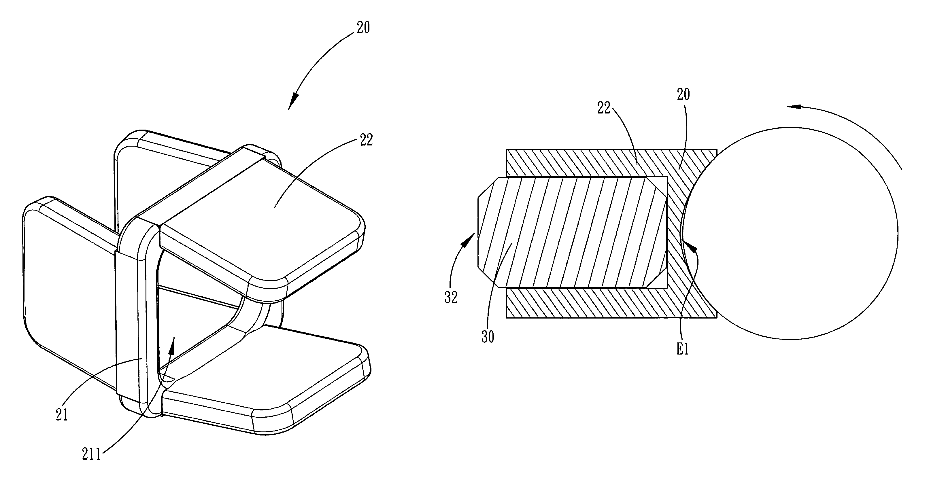
[0039]Due to the space 211 is formed in the frame 21 of the spacer 20 for ensuring a linear contact between the rolling surface 32 of the roller 30 and the frame 21, plus the protruding wings 22 are arranged in pairs on opposing sides of the frame 21 and outwardly extend therefrom (the semi-circular stopping portion 221 is formed at the end of the respective protruding wings 22), and the two inactive end surfaces 31 of the roller 30 are confined between the paired protruding wings 22 of the spacer 20, and the slenderness ratio of the roller 30 is designed to be 0.7-0.98, it can produce the receiving clearance A for accommodation of the stopping portion 221 of the respective protruding wings 22. Hence, the combination of the abovementioned arrangements can prevent an overlarge friction be...

fourth embodiment

[0042]Referring then to a fourth embodiment as shown in FIGS. 9 and 10.

[0043]The spacer 20 is made of elastic material and comprises a frame 21 and four protruding wings 22. The frame 21 is formed with a space 211. The protruding wings 22 are arranged in pairs on opposing sides of the frame 21 and outwardly extend therefrom, and the respective oppositely arranged protruding wings 22 are inclined a predetermined angle D1 toward each other, so that the ends of the paired opposite protruding wings 22 taper to form a minimum distance D2, and the minimum distance D2 is smaller than or equal to the distance between the two end surfaces of the roller.

[0044]The design concept of the fourth embodiment is quiet opposite to that of the previous embodiments, the fourth embodiment is aimed at reducing the friction effect of the protruding wings 22 of the spacer 20. Since the respective oppositely arranged protruding wings 22 are inclined a predetermined angle D1 toward each other, and the minimu...

fifth embodiment

[0045]Referring finally to FIG. 11, which shows the present invention, the space of the frame 21 of the spacer 20 can be in the form of a Gothic type groove El, thus ensuring that the rolling surface 32 of the roller 30 keeps in a linear contact with the frame 21.

[0046]The present invention is applicable to various cross-roller type linear transmission apparatuses, including linear guideway, ball screw, and any other linear transmission apparatus with cross roller would be considered within the scope of the present invention.

[0047]To summarize, the innovated design of the present invention is characterized in that the spacer comprises a frame and four protruding wings, the protruding wings are arranged in pairs on opposing sides of the frame and outwardly extend therefrom. The two inactive end surfaces of the roller are confined between the paired protruding wings of the spacer. The slenderness ratio of the roller is designed to be 0.7-0.98 for facilitating installation of the rolle...


PUM


Abstract

A spacer structure for cross rollers comprises a frame and four protruding wings, the protruding wings are arranged in pairs on opposing sides of the frame and outwardly extend therefrom. The two inactive end surfaces of the roller are confined between the paired protruding wings of the spacer. The slenderness ratio of the roller is designed to be 0.7-0.98 for facilitating installation of the roller between the paired protruding wings of the spacer, and such arrangement can effectively reduce the contact area between the spacer and the roller. The paired opposite protruding wings can provide a stable positioning effect to the end surfaces of the roller.

Description

BACKGROUND OF THE INVENTION[0001]1. Field of the Invention[0002]The present invention relates to a spacer for a linear transmission apparatus, and more particularly to a spacer for cross rollers, which can make the roller move stably and can effectively reduce the contact area between the spacer and the roller, and also have a stable positioning function.[0003]2. Description of the Prior Art[0004]Since linear transmission products are being applied more and more widely in the modern industry, various linear transmission mechanisms have widely come into human life, manufacturing factory and high science and technology instruments, such as linear guideway, ball screw, and the like. Particularly in a large-scale precision mechanism are usually installed various large and small ball screws or linear guideway systems. Although the technology for linear transmission element is developing fast, consumers still need the technology to be improved uninterruptedly. Therefore, there are still s...

Claims


Application Information

Patent Timeline
Patent Type & Authority Patents(United States)
IPC IPC(8): F16C19/40
CPCF16C29/041F16C33/37F16C33/508F16C2240/40
Inventor CHEN, YAN-YU
Owner HIWIN TECH
Why Eureka
Try Eureka