Mounting bracket for electrical box

a technology for mounting brackets and electrical boxes, which is applied in the direction of machine supports, installation of lighting conductors, and coupling device connections, etc., can solve the problems of cumbersome brackets and their mounting features, inability to quickly and easily attach to studs, and difficult alignment of boxes that attach directly to studs

Active Publication Date: 2008-10-21
THOMAS & BETTS INT INC
View PDF24 Cites 46 Cited by
  • Summary
  • Abstract
  • Description
  • Claims
  • Application Information

AI Technical Summary

Problems solved by technology

Prior art electrical boxes that attach directly to a stud are difficult to align and the front of the box often does not align with the outer wall covering.
However, many of these brackets and their mounting features are cumbersome and cannot be quickly and easily attached to a stud.

Method used


Image

  • Mounting bracket for electrical box
  • Mounting bracket for electrical box
  • Mounting bracket for electrical box

Examples


first embodiment

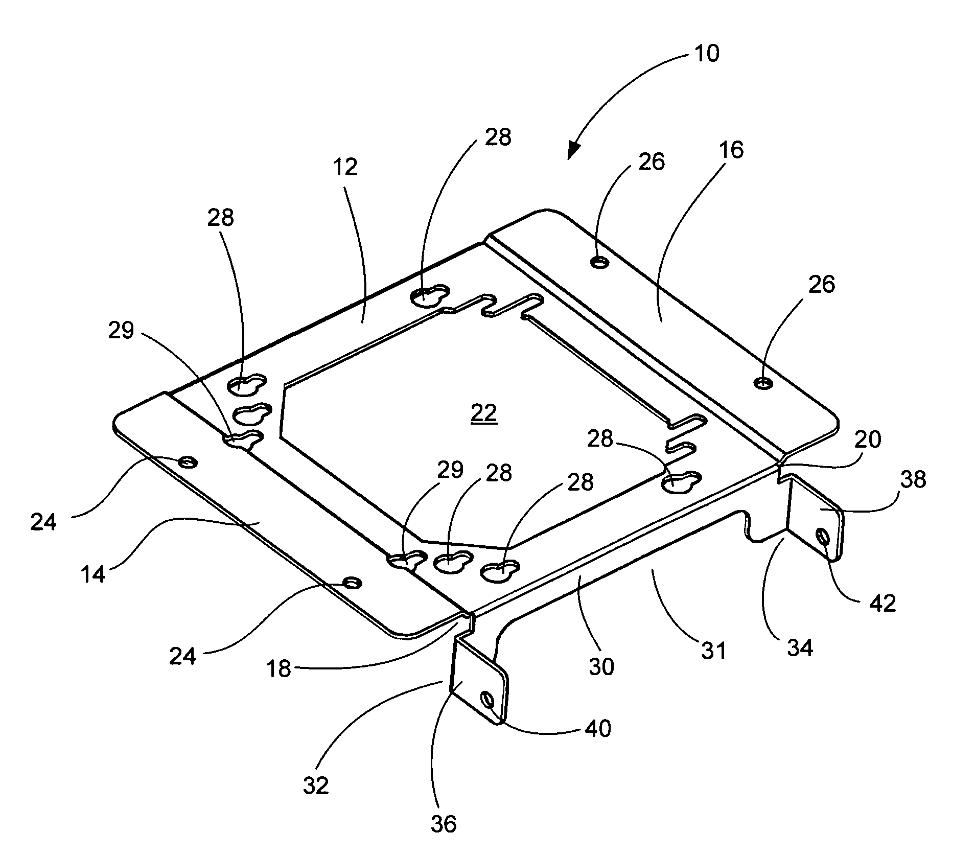
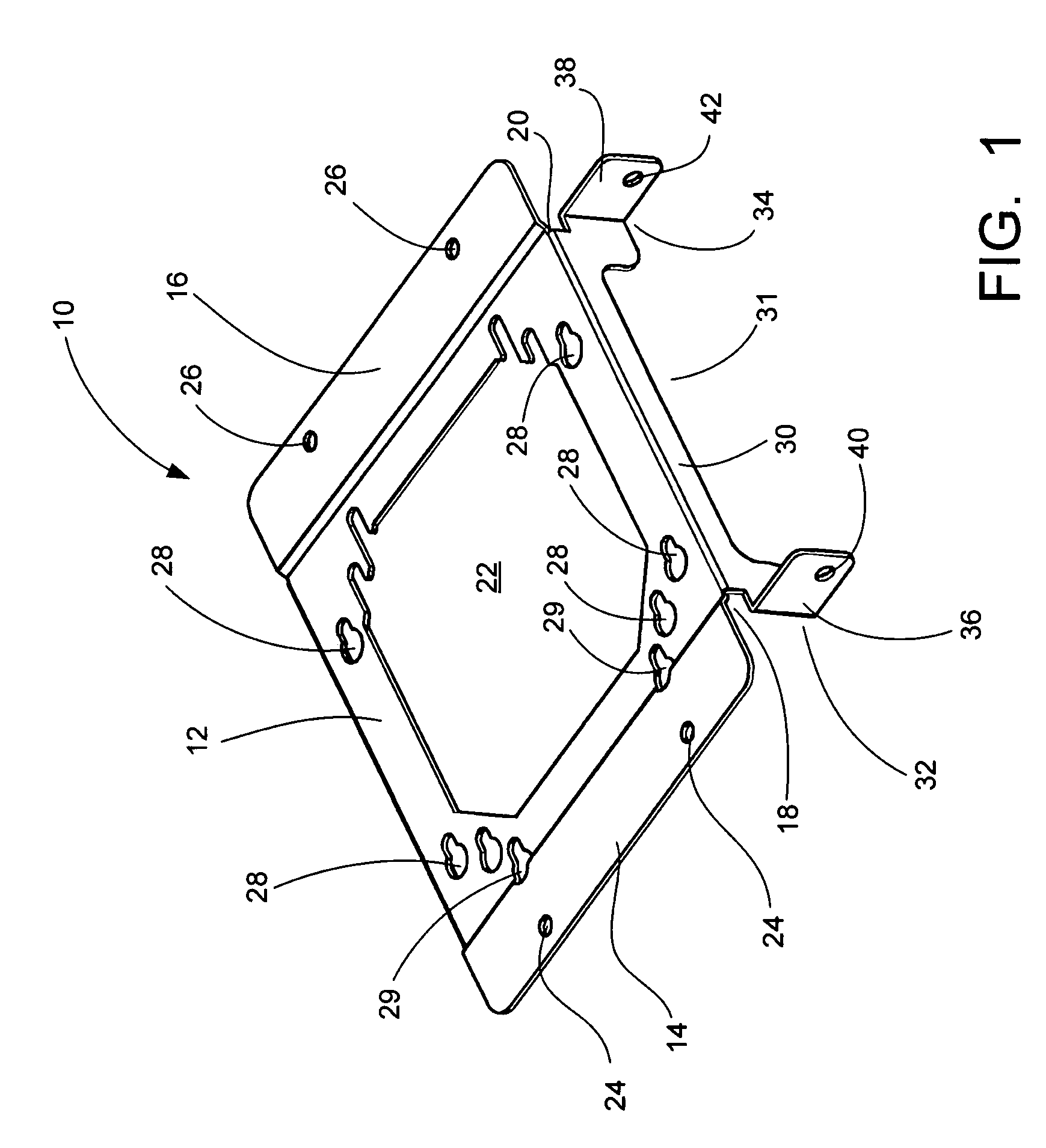
[0026]FIG. 1 shows a front perspective view of the mounting bracket 10 used for an electrical box 90 (see FIG. 4). The bracket 10 includes a base plate 12 with flanges 14, 16 connected to the opposing sides by flange necks 18, 20. The surfaces of the flanges 14, 16 are parallel to, and also preferably offset from (but not necessarily), the plane formed by the surface of the base plate 12 and include a plurality of holes or apertures 24, 26 for securing the bracket 10 to a structure, preferably a wall stud 80 (see FIG. 3). In this fashion, either side of the bracket 10 may be mounted to the stud. The surface of the base plate 12 is, preferably, recessed from the surfaces of the flanges 14, 16 so that the mounting surface of a cover plate 92 (see FIG. 4) attached to the electrical box 90 will not extend beyond the surfaces of the flanges 14, 16.

[0027]The first embodiment of the bracket 10 also has a wall 30 which extends from at least one of the ends of the base plate 12. Its directio...

second embodiment

[0034]FIG. 6 shows a front perspective view of the mounting bracket 110 used for an electrical box 190 (see FIG. 9). The bracket 110 includes a base plate 112 with flanges 114, 116 connected to the opposing sides by flange necks 118, 120. The surfaces of the flanges 114, 116 are parallel to, and also preferably offset from (but not necessarily), the plane formed by the surface of the base plate 112 and include a plurality of holes 124, 126 for securing the bracket 110 to a structure, preferably a wall stud 180 (see FIG. 8). In this fashion, either side of bracket 110 may be mounted to the stud. The surface of the base plate 112 is, preferably, recessed from the surfaces of the flanges 114, 116 so that the mounting surface of a cover plate 192 (see FIG. 9) attached to the electrical box 190 will not extend beyond the surfaces of the flanges 114, 116.

[0035]The second embodiment of the bracket 110 also has a wall 130 which extends from at least one of the ends of the base plate 112. It...


PUM


Abstract

A mounting bracket for an electrical box that includes: a base plate having substantially planar top and bottom surfaces, a first side, a second side, a first end, a second end, a plurality of mounting screw apertures and an opening for receiving an electrical box; a first flange and a second flange connected to the first and second sides, respectively, of the base plate by a first flange neck and a second flange neck, wherein each flange has a top and a bottom flange surface, wherein the flange necks extend from the top surface of the base plate; a wall connected to the first end having a substantially flat outer wall surface and a pair of opposing ends, wherein the wall extends from the bottom surface of the base plate; and a tab connected to each opposing end of the wall, wherein the tabs are substantially perpendicular to the outer surface of the wall.

Description

[0001]This application claims priority from provisional applications Ser. No. 60 / 773,422, filed on Feb. 15, 2006 which is incorporated herein in its entirety.FIELD OF THE INVENTION[0002]The present invention is a mounting bracket for an electrical box. In particular, the present invention relates to a mounting bracket for an electrical box that provides additional support when the bracket is mounted to a stud.BACKGROUND OF INVENTION[0003]An electrical box provides an enclosure for an electrical receptacle as well as a termination point for wires carrying electrical current. Wiring entering an electrical box is typically connected to an electrical fixture or receptacle, such as a plug outlet or switch. The box can then be covered by a face plate having an opening, which allows access to the outlet or switch while preventing electrified components from being exposed. For most applications, the electrical box is surface mounted with the wiring to the box concealed in a wall or ceiling....

Claims


Application Information

Patent Timeline
Patent Type & Authority Patents(United States)
IPC IPC(8): H01H9/02
CPCH02G3/126Y10S248/906
Inventor DINH, CONG THANH
Owner THOMAS & BETTS INT INC
Why Eureka
Try Eureka