Hinge system for low-profile cabinet assemblies

a cabinet assembly and hinge technology, applied in the direction of electrical apparatus casings/cabinets/drawers, coupling device connections, instruments, etc., can solve the problems of limited space to include hinges, inability to design and/or implement installations that are intended to support super fast data transmission, and lack of hinges. , to achieve the effect of low profile design, easy access to internal components, and limited spa

Active Publication Date: 2008-10-21
ORTRONICS INC
View PDF13 Cites 68 Cited by
  • Summary
  • Abstract
  • Description
  • Claims
  • Application Information

AI Technical Summary

Benefits of technology

[0009]The present disclosure provides an advantageous hinge mechanism / hinge design that facilitates access to internal components associated with a cabinet, e.g., a fiber optic cabinet. In particular, the disclosed hinge mechanism / hinge design is adapted for use with a telecommunication cabinet that is of low profile design, e.g., 1U or 2U height. According to exemplary embodiments of the present disclosure, the hinge mechanism is adapted for a combination of motions, e.g., a sliding motion and a hinging motion, whereby the limited space associated with a low profile cabinet is overcome and advantageous access to internal componentry, e.g., patch panels and the like, is facilitated.

Problems solved by technology

In many instances, installations that are intended to support super fast transmission of data are no longer being designed and / or implemented with relatively low bandwidth copper cabling.
In the case of a 1U design, i.e., a low profile cabinet, there is typically limited space to include a hinge and accommodate the installation of patch panels and / or MPO (multi-fiber push-on) cassettes.
However, the absence of a hinged door is an undesirable configuration because, inter alia, the front door becomes difficult to securely lock and removal is required each time patch cord installation and / or moves, adds or changes are required.

Method used


Image

  • Hinge system for low-profile cabinet assemblies
  • Hinge system for low-profile cabinet assemblies
  • Hinge system for low-profile cabinet assemblies

Examples


Embodiment Construction

)

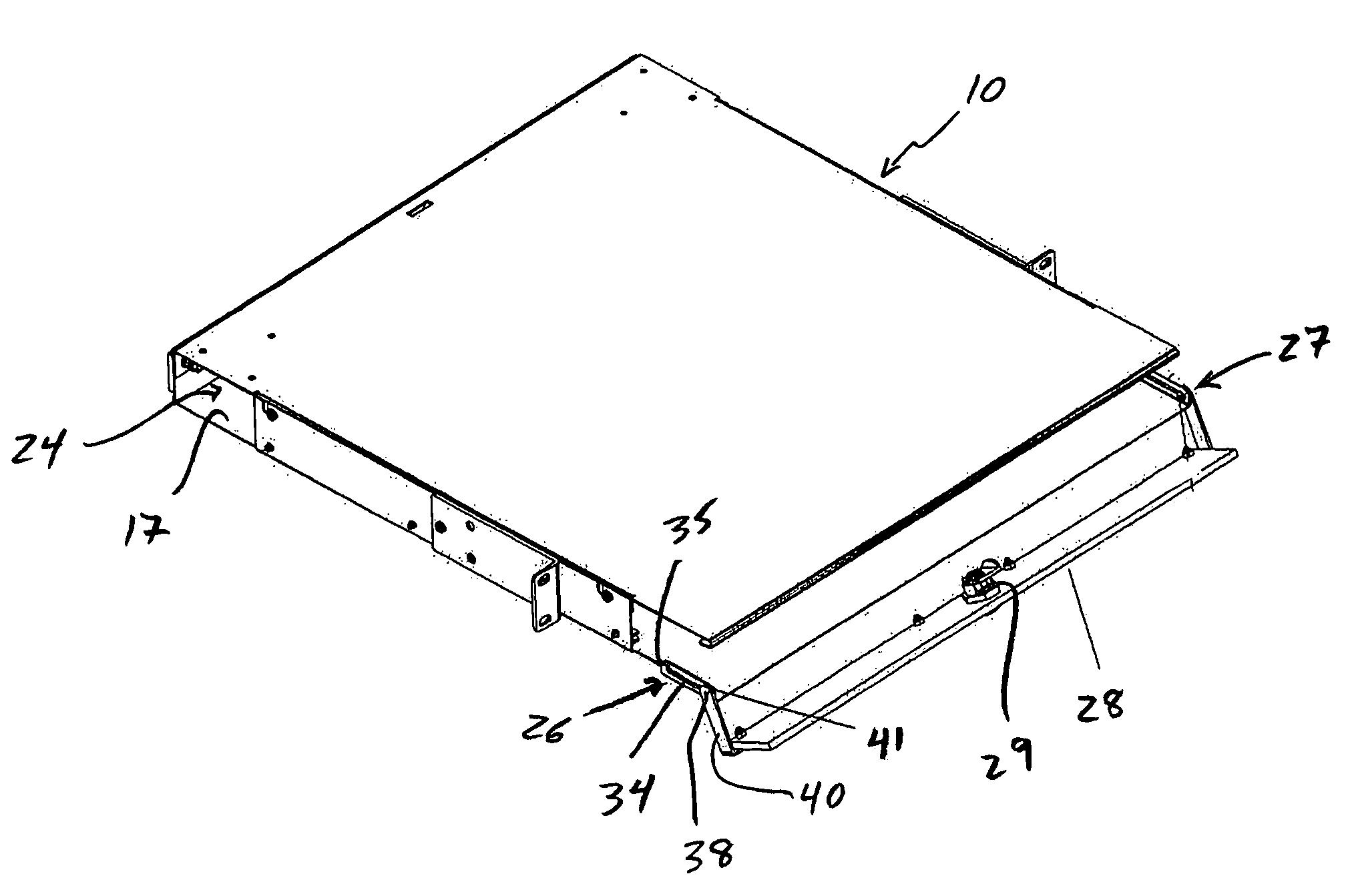
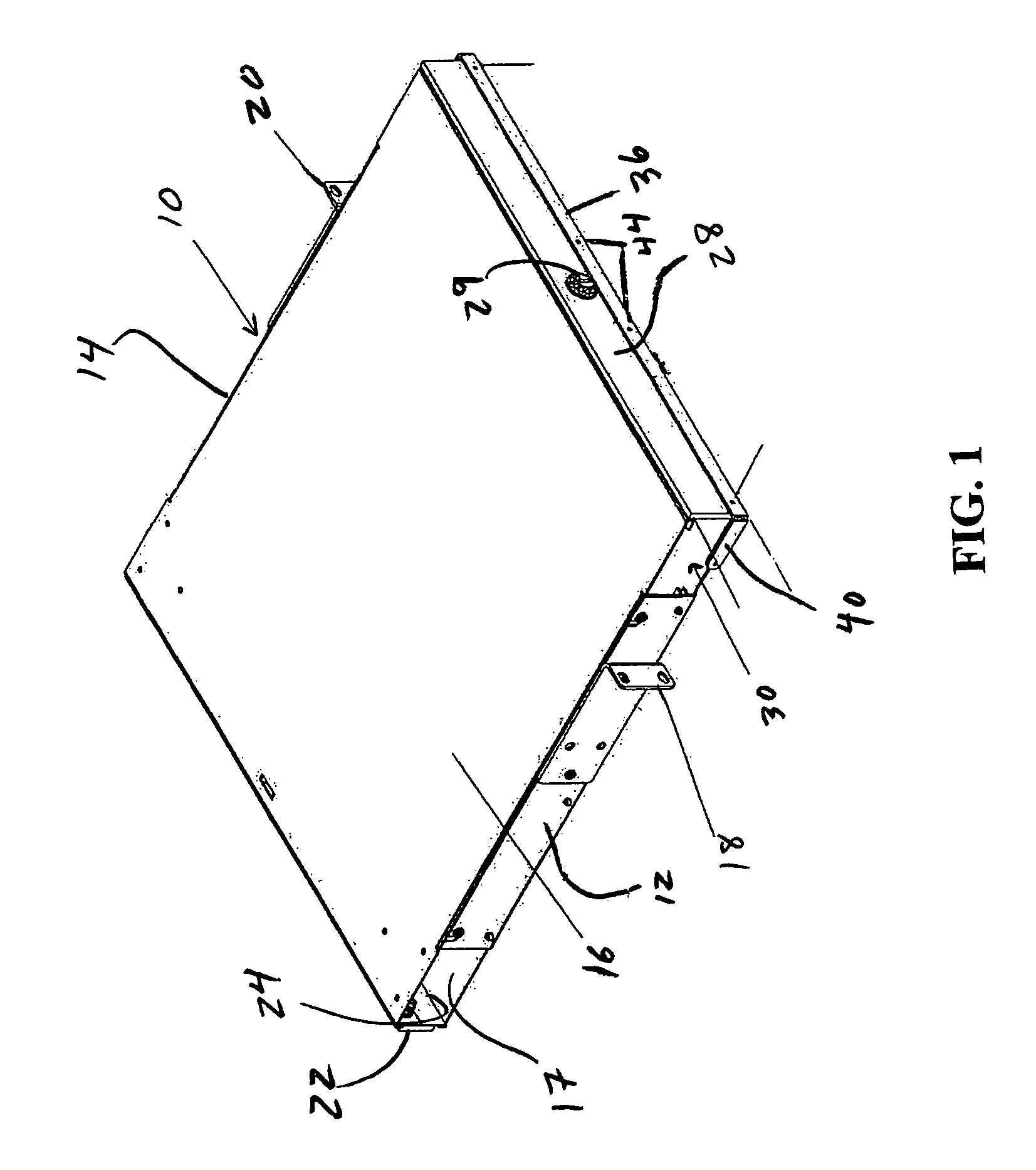
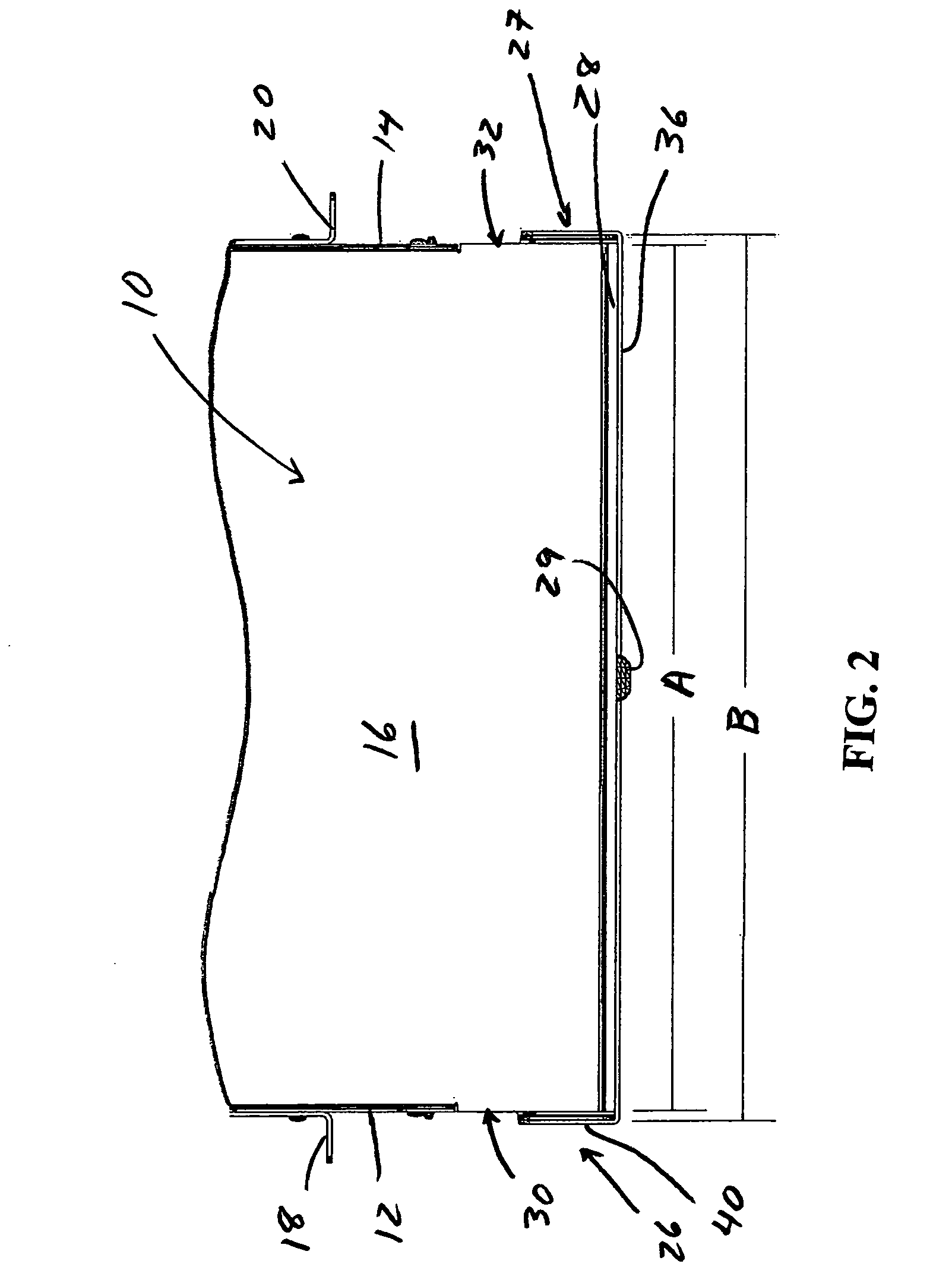
[0018]Advantageous hinge mechanisms and hinge designs are provided according to the present disclosure. Although the disclosed hinge mechanisms and hinge designs are particularly beneficial in applications where the associated enclosure is of low profile design, the disclosed hinge mechanisms / hinge designs are susceptible to wide ranging applications. The disclosed hinge systems and hinge designs generally facilitate access to internal components associated with an enclosure, e.g., a fiber optic cabinet. In particular applications, the disclosed hinge mechanisms and / or hinge designs may be used with a telecommunication cabinet that is of low profile design, e.g., 1U or 2U height. According to exemplary embodiments of the present disclosure, the hinge mechanism is adapted for a combination of motions, e.g., a sliding motion and a hinging motion, whereby issues associated with a low profile enclosure / cabinet are advantageously overcome and ready access to internal componentry, e.g., ...


PUM


Abstract

Hinge mechanisms that facilitates access to internal components associated with a cabinet, e.g., a fiber optic cabinet, are provided. The hinge mechanisms are adapted for use with a telecommunication cabinet that is of low profile design, e.g., 1U or 2U height. The hinge mechanisms accommodate a combination of motions, e.g., a sliding motion and a hinging motion, whereby the limited space associated with a low profile cabinet is overcome and access to internal componentry, e.g., patch panels, is facilitated. A pair of hinge mechanisms are provided with a door. The hinge mechanisms mount outward of the cabinet so as to permit the door to be pivoted downward without engagement between with another cabinet or other structure positioned therebelow. A U-shaped member may be mounted to the door and sliding pins to translate motion from the hinge mechanisms to the door.

Description

BACKGROUND[0001]1. Technical Field[0002]The present disclosure is directed to advantageous hinge systems and, more particularly, to hinge systems having particular utility in telecommunication cabinet applications, e.g., low profile cabinet assemblies.[0003]2. Background Art[0004]As the world's telecommunication speeds have increased, the speed of Local Area Networks and other facility-based networks have increased as well. Large data centers and storage area networks have become commonplace, particularly in new facility construction. In many instances, installations that are intended to support super fast transmission of data are no longer being designed and / or implemented with relatively low bandwidth copper cabling. Rather, installations are increasingly incorporating fiber optic transmission systems, at least in part to provide backbone support / infrastructure for new and upgraded installations.[0005]In typical fiber optic structured cabling systems, fiber optic patching typicall...

Claims


Application Information

Patent Timeline
Patent Type & Authority Patents(United States)
IPC IPC(8): H02G3/08
CPCG02B6/4455Y10T292/1082
Inventor MURANO, ADAMRYNASKI, CHESTER H.
Owner ORTRONICS INC
Why Eureka
Try Eureka