Electromagnetic relay

a technology of electromagnetic relays and relays, applied in electromagnetic relays, electrical apparatus, electromagnetical relay details, etc., can solve problems such as malfunctioning relays, achieve large electric currents, ensure durability and contact stability, and reduce internal resistance

Active Publication Date: 2008-10-21
UCHIYA THERMOSTAT
View PDF6 Cites 10 Cited by
  • Summary
  • Abstract
  • Description
  • Claims
  • Application Information

AI Technical Summary

Benefits of technology

[0008]A technological challenge arises to reduce the internal resistance as much as possible on the contact circuit side and flow large currents as well as to improve the contact function of small electromagnetic relays with one-circuit 3-contact gap, and the objective of this invention is to resolve this challenge.

Problems solved by technology

For this reason, you cannot reduce the internal resistance on the contact circuit side, and if you are to use a moveable contact plate which has contact with the aim of reducing the internal resistance, you will have to use a thicker plate, a stronger spring and heavier moveable contact 9, which may cause such relays to malfunction when they receive some kind of shocks.

Method used


Image

  • Electromagnetic relay
  • Electromagnetic relay
  • Electromagnetic relay

Examples


Embodiment Construction

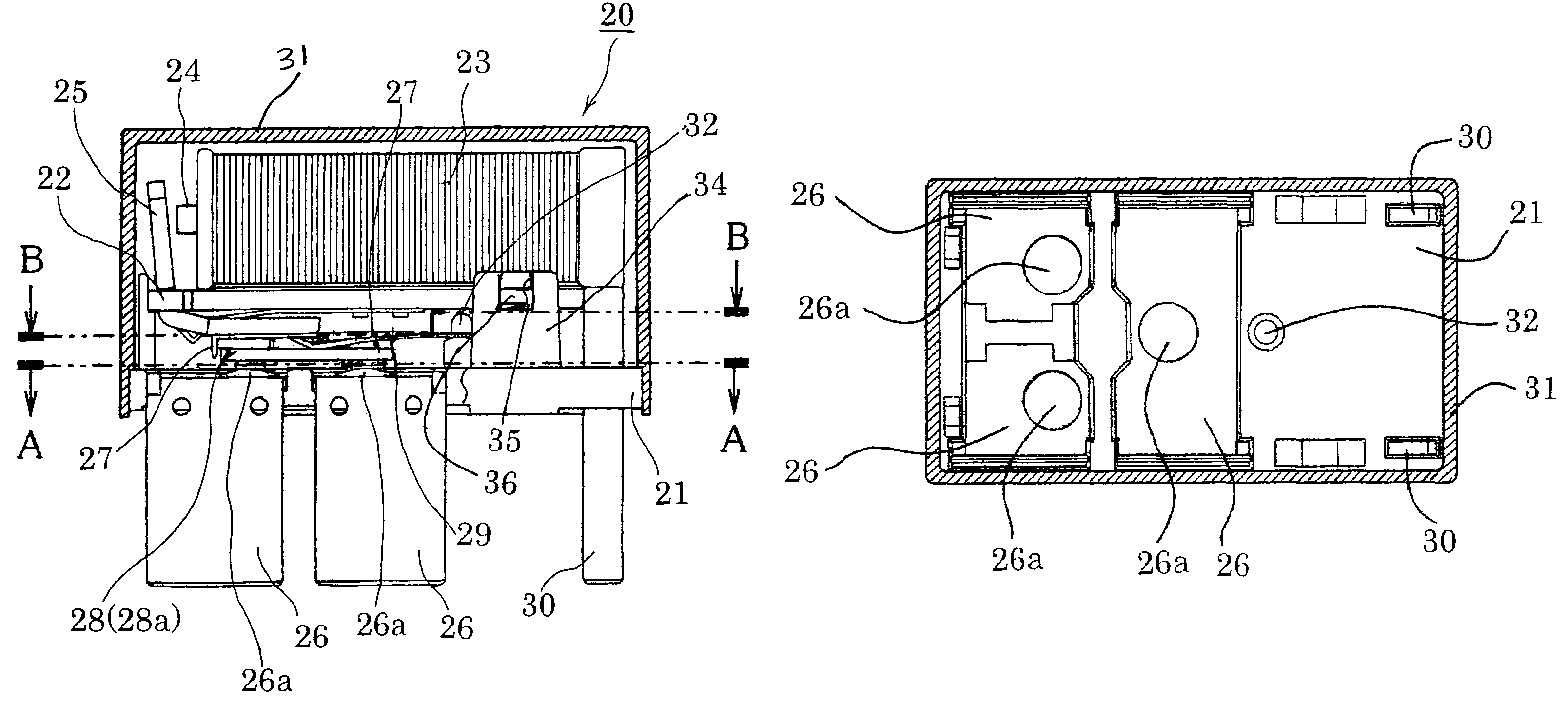
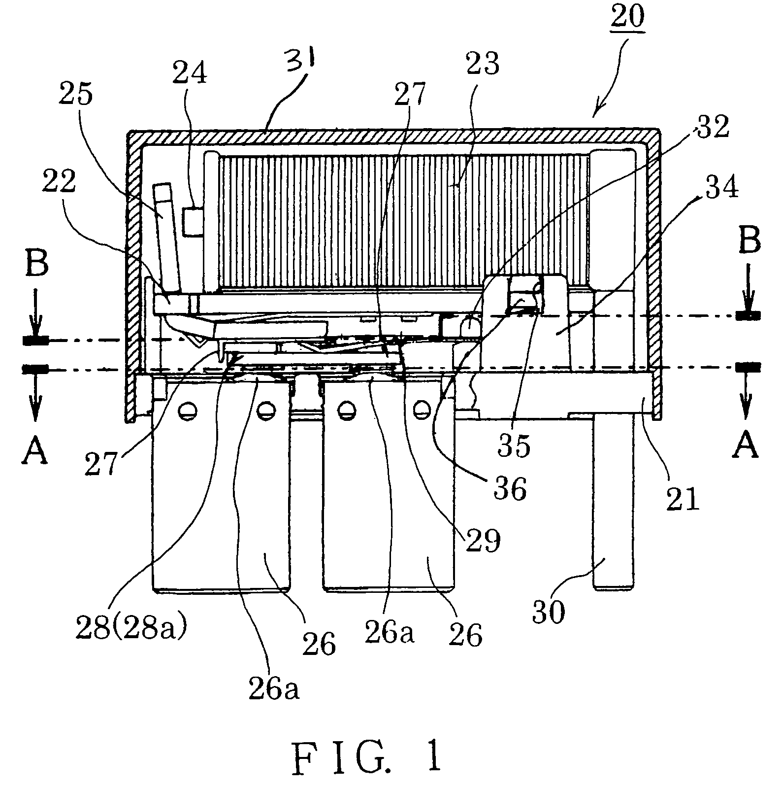
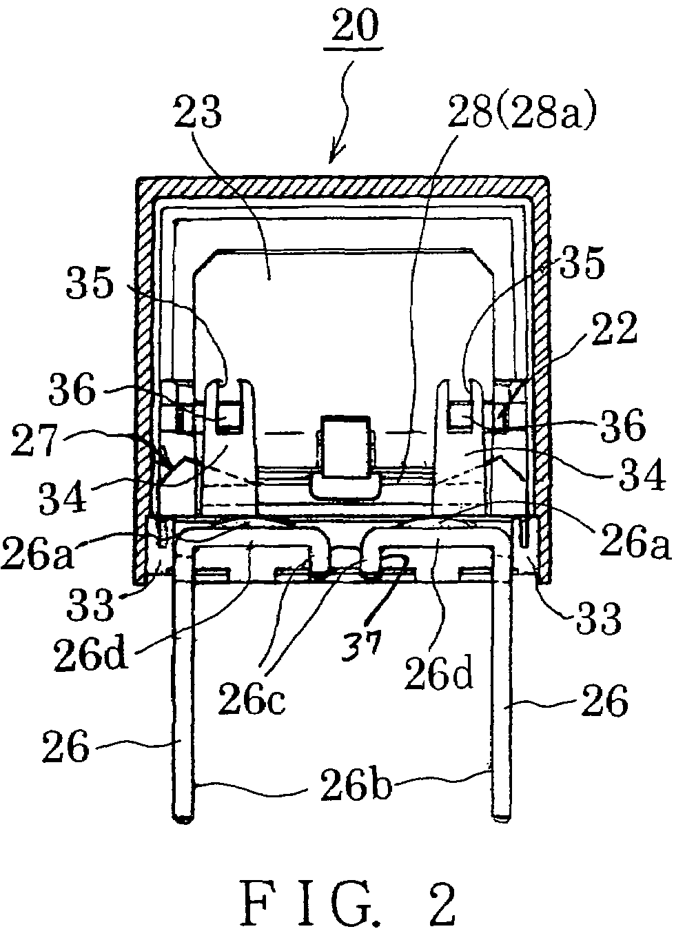
[0030]We would like to provide detailed explanations about a preferred embodiment of this invention by using FIG. 1 to FIG. 11. FIG. 1 shows an electromagnetic relay 20 of this invention. This electromagnetic relay 20 consists of a thick insulation base 21 like a flat panel, which is produced through a molding method, yoke 22, coil 23, iron core 24, armature 25, fixed terminals 26 fixed contacts 26a, which are respectively installed on fixed terminals 26, moveable springs 27, moveable plate 28, which is supported and fastened by moveable springs 27, moveable contacts 28a, which connect or disconnect with fixed contacts 26a, elastic plate 29, which elastically pressure-releases moveable springs 27, coil terminal 30 and cap 31. The electromagnetic relay 20 shown in FIG. 1 is an electromagnetic relay with one-circuit three-contact gap as schematically shown in the circuit diagram of FIG. 11.

[0031]The electromagnetic relay 20 is structured so that the armature 25 drives the moveable spr...


PUM


Abstract

To reduce the internal resistance of small electromagnetic relays of a one-circuit three-contact gap type in order to make it possible to allow large electric currents and at the same time to improve the connection between the fixed contacts and the moveable contacts. Fixed contacts on the fixed terminals are positioned at each apex of an approximate triangle on the upper surface of the insulation base. Moveable contacts are installed on the lower surface of the moveable plate, and are respectively placed in a position which corresponds to each of the fixed contacts. The moveable plate is fastened to the moveable spring whose both ends are held onto the sides of the insulation base, and moves at a specified distance from the fixed contacts due to the pressure of the moveable spring. The construction results in the movable contacts contacting their corresponding fixed contacts at the three positions with uniform contact strength.

Description

BACKGROUND OF THE INVENTION[0001]1. Field of the Invention[0002]This invention is concerning a new type of electromagnetic relay. Especially, it is concerning small electromagnetic relays whose internal resistance on the contact circuit side of an electromagnetic relay with the one-circuit three-contact gap has been reduced as much as possible and for which necessary improvements have been made to be able to allow the flow of large electric currents.[0003]2. Description of the Related Art[0004]First, we would like to explain about a conventional small electromagnetic relay 1 in accordance with FIG. 12. FIG. 12 is a vertical side view showing the outline of electromagnetic relay 1. The electromagnetic relay 1 shown therein consists of yoke 3 vertically installed on insulation base 2, which was mold-produced, Iron Core 4 which was fastened onto the Yoke 3, Coil 5, which was wound around a bobbin with iron core 4 being placed in the center, armature 6, which was installed to be able to...

Claims


Application Information

Patent Timeline
Patent Type & Authority Patents(United States)
IPC IPC(8): H01H51/22
CPCH01H50/041H01H50/54
Inventor MOCHIZUKI, NAOYATAKEDA, HIDEAKI
Owner UCHIYA THERMOSTAT
Why Eureka
Try Eureka