Electrical bus member mounting system and electrical enclosure employing the same

a technology of electrical enclosure and mounting system, which is applied in the direction of substation/switching arrangement casing, non-enclosed substation, substation, etc., can solve the problems of unnecessarily large size, ineffective allocation of interior space within the enclosure, and occupying substantial floor space of enclosures. to achieve the effect of facilitating access

Active Publication Date: 2008-10-21
EATON INTELLIGENT POWER LTD
View PDF10 Cites 17 Cited by
  • Summary
  • Abstract
  • Description
  • Claims
  • Application Information

AI Technical Summary

Problems solved by technology

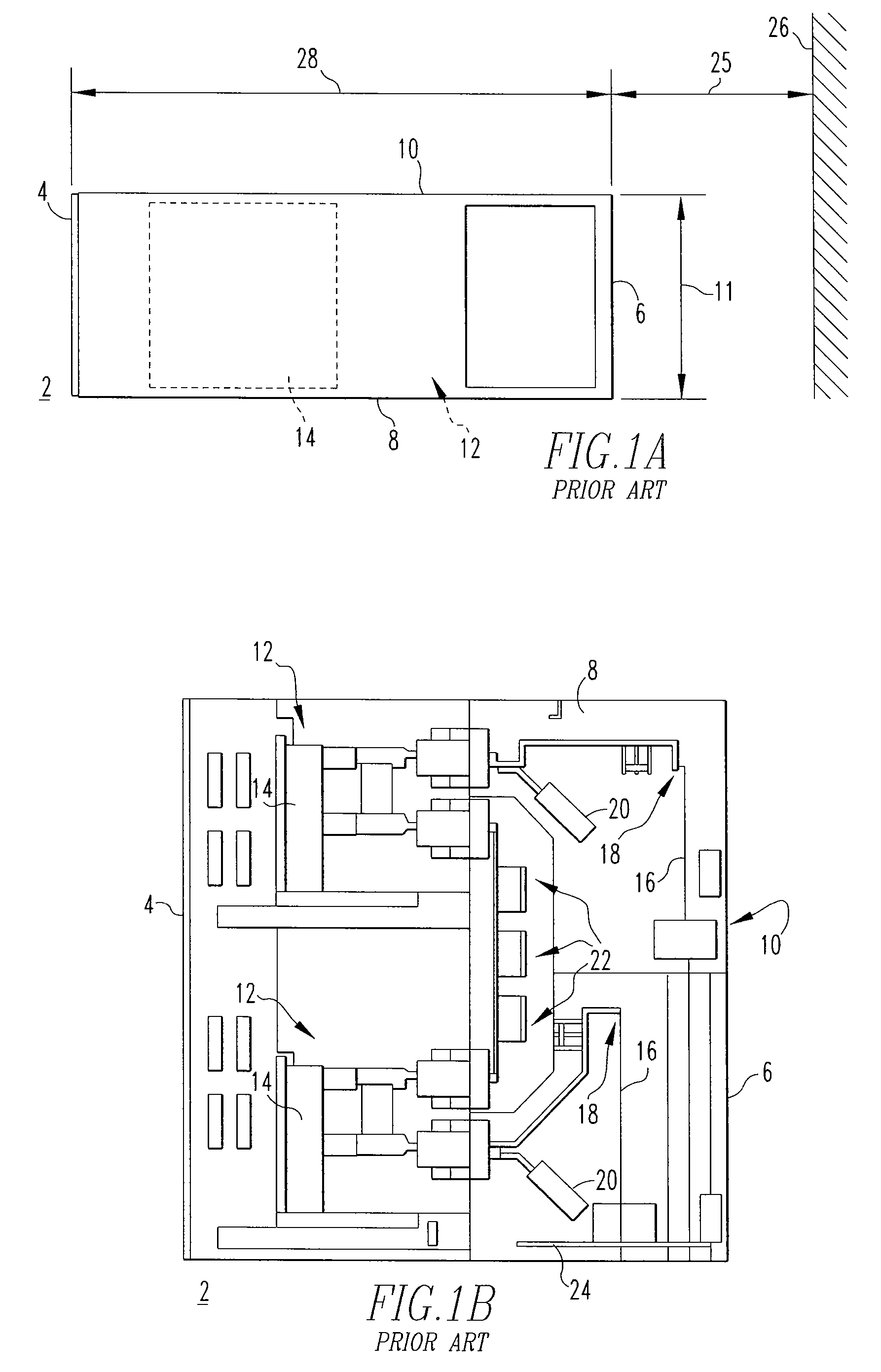
Such enclosures have been known to take up substantial floor space.
Among them is the fact that they are unnecessarily large in size, and suffer from an ineffective allocation of the interior space within the enclosure.
These disadvantages contribute to the undesirable inefficient use of a significant amount of valuable floor space.
Accordingly, a significant amount of valuable floor space is undesirably occupied by the cabinet 2, as previously discussed.

Method used


Image

  • Electrical bus member mounting system and electrical enclosure employing the same
  • Electrical bus member mounting system and electrical enclosure employing the same
  • Electrical bus member mounting system and electrical enclosure employing the same

Examples


Embodiment Construction

[0025]For purposes of illustration, embodiments of the invention will be described as applied to switchgear cabinets housing one or more switchgear devices, such as circuit breakers, although it will become apparent that it could also be applied to provide unobstructed front access to a wide range of electrical bus members for any known or suitable electrical apparatus disposed within an electrical enclosure.

[0026]Directional phrases used herein, such as, for example, left, right, front, back, top, bottom and derivatives thereof, relate to the orientation of the elements shown in the drawings and are not limiting upon the claims unless expressly recited therein.

[0027]As employed herein, the term “section” refers to an interior portion, defined area, compartment, portion of a compartment, or particular region within an electrical enclosure.

[0028]As employed herein, a “switchgear apparatus” expressly includes, without limitation, any known or suitable switchgear device which is struct...


PUM


Abstract

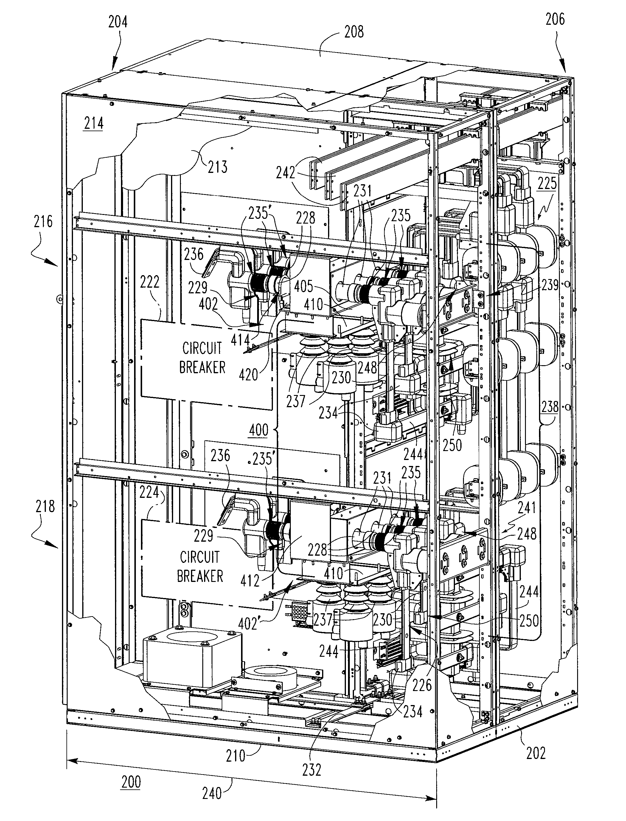
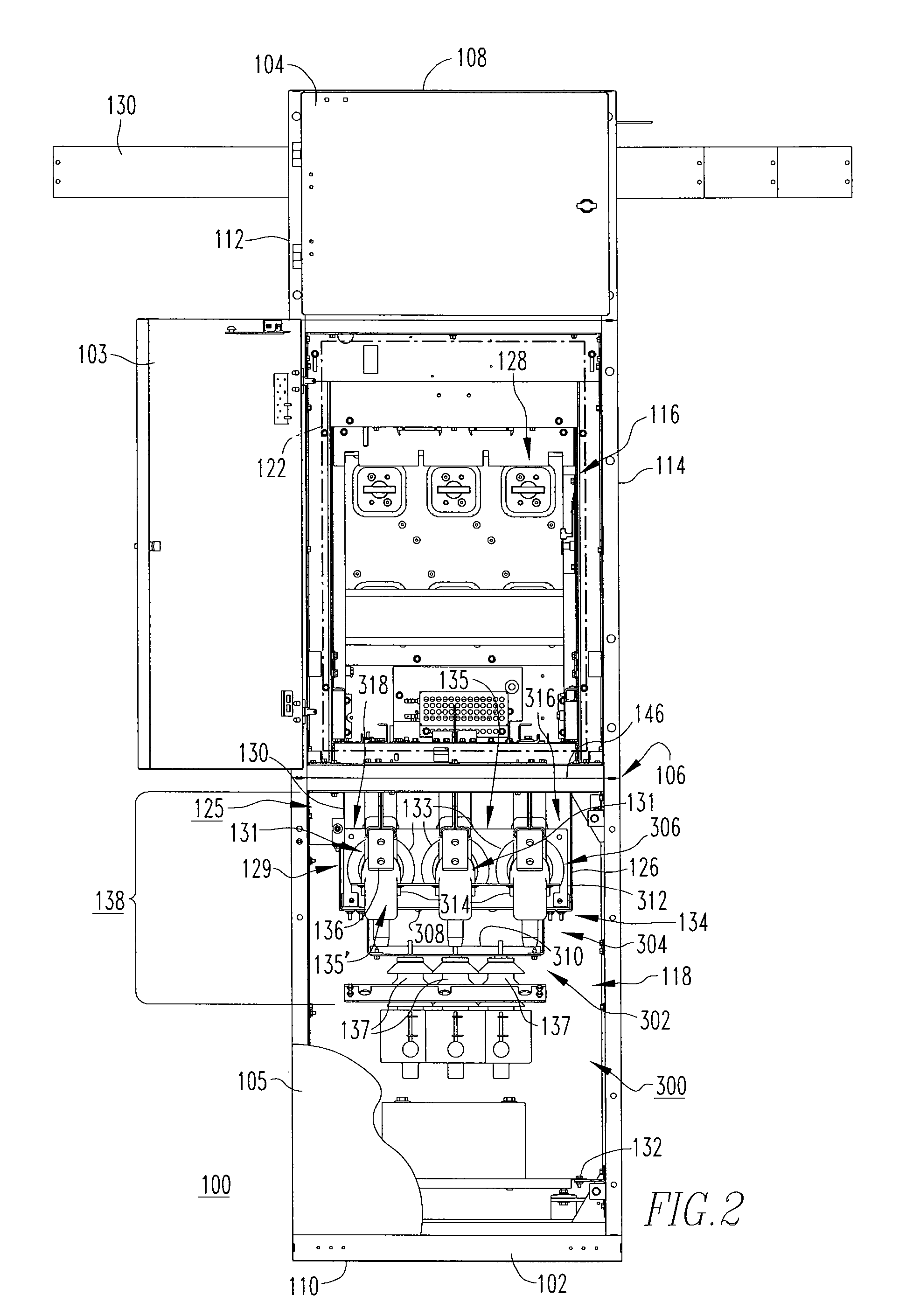
An electrical bus member mounting system is provided for an electrical enclosure including a housing having a front, a back and a plurality of sides, a plurality of sections disposed between the sides, at least one electrical apparatus disposed within a first one of the sections, and an electrical bus assembly electrically connected to the electrical apparatus. The electrical bus member mounting system includes a mounting assembly having a first portion and a second portion. A plurality of electrical bus members are coupled to the first portion and the second portion is coupled at or about at least one of the sides of the housing within a second one of the sections thereof. Accordingly, the electrical bus member mounting system consolidates a substantial portion of the electrical bus assembly at a single location within the second one of the sections of the housing, in order to facilitate access thereto.

Description

CROSS-REFERENCE TO RELATED APPLICATION[0001]This application is related to commonly assigned, concurrently filed:[0002]U.S. patent application Ser. No. 11 / 530,113, filed Sep. 8, 2006, entitled “Front Access Electrical Enclosure and Electrical Bus Assembly Therefor”, which is hereby incorporated herein by reference.BACKGROUND OF THE INVENTION[0003]1. Field of the Invention[0004]The invention relates generally to electrical enclosures and, more particularly, to an electrical bus member mounting system for an electrical enclosure. The invention also relates to electrical enclosures having electrical bus members.[0005]2. Background Information[0006]A significant goal with regard to power distribution systems in, for example, commercial applications, such as commercial construction applications, is to be cost effective. As such, maintenance and space considerations are driving factors in the design of new electrical equipment. Specifically, the equipment should be easy to maintain in ord...

Claims


Application Information

Patent Timeline
Patent Type & Authority Patents(United States)
IPC IPC(8): H02B1/14
CPCH02B1/21H02B1/20
Inventor PARKER, PAUL K.SMITH, JAMES E.COLBAUGH, PAUL A.SCIALABBA, MARCY D.CARDER, RONALD A.
Owner EATON INTELLIGENT POWER LTD
Why Eureka
Try Eureka