Computer enclosure with drive bracket

a technology of drive brackets and enclosures, which is applied in the direction of electric apparatus casings/cabinets/drawers, instruments, record information storage, etc., can solve the problems of cumbersome and time-consuming security means

Inactive Publication Date: 2008-10-21
HONG FU JIN PRECISION IND (SHENZHEN) CO LTD +1
View PDF4 Cites 10 Cited by
  • Summary
  • Abstract
  • Description
  • Claims
  • Application Information

AI Technical Summary

Benefits of technology

[0006]A computer enclosure includes a chassis with an opening defined therein, an elastic piece, a first drive bracket secured in the chassis, and a second drive bracket. One end of the elastic piece is secured to the chassis adjacent the opening, and the other end of the elastic piece is free and forms a protrusion thereon. The second drive bracket defines a hole therein corresponding to the protrusion. The second drive bracket extends through the opening from an outside of the chassis to pull the protrusion and elastically bend the elastic piece, and then slides on the first drive bracket until the protrusion of the elastic piece is in alignment with the hole of the first drive bracket, the elastic piece rebounds to have the protrusion inserted into the hole to secure the second drive bracket on the first drive bracket.

Problems solved by technology

However, such securing means are cumbersome and time-consuming. FIG. 5 shows an improved computer enclosure with a first drive bracket 100′ and a second drive bracket 200′.

Method used


Image

  • Computer enclosure with drive bracket
  • Computer enclosure with drive bracket
  • Computer enclosure with drive bracket

Examples


Embodiment Construction

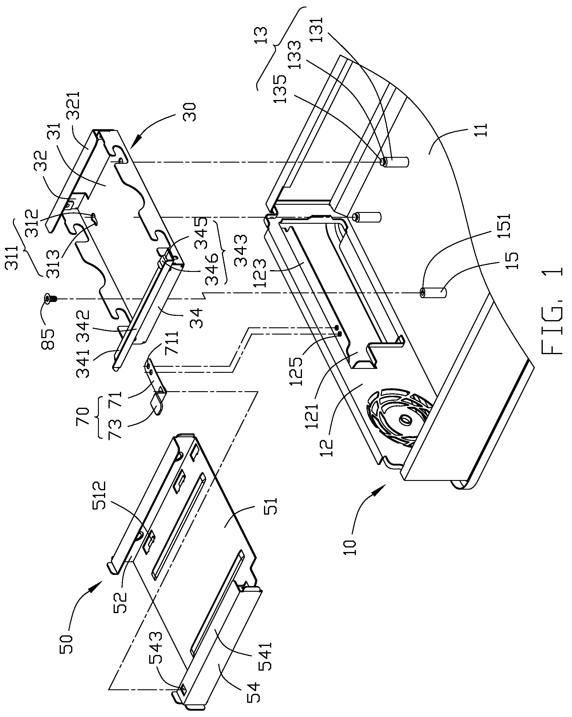
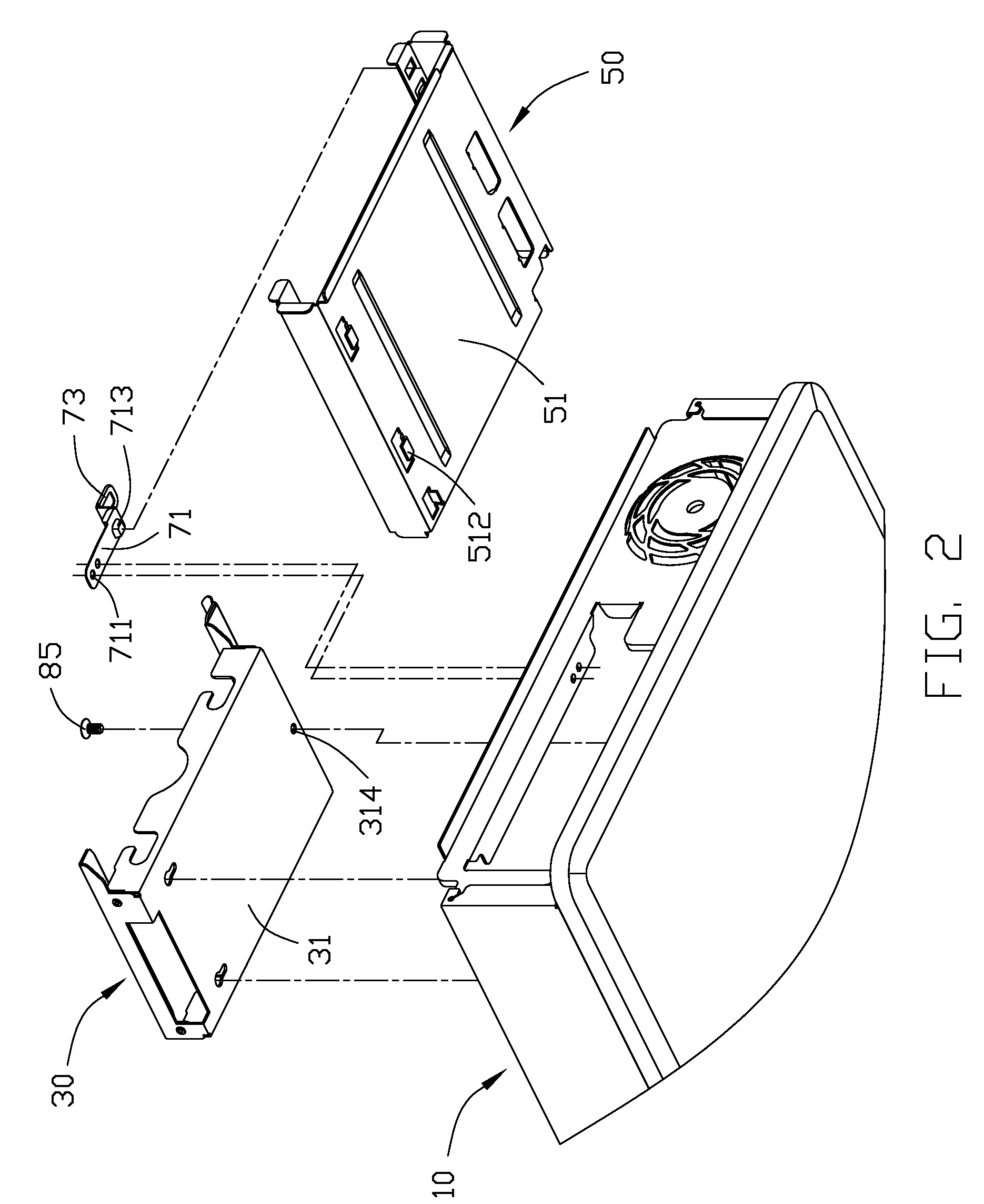
[0013]Referring to FIG. 1, a computer enclosure in accordance with a preferred embodiment of the present invention includes a chassis 10, a first drive bracket 30, and a second drive bracket 50.

[0014]The chassis 10 includes a bottom wall 11 and a side wall 12 extending perpendicularly and upwardly from a front edge of the bottom wall 11. A pair of posts 13 is formed upwardly on the bottom wall 11. Each of the posts 13 includes a shank portion 131 connected with the bottom wall 11, a neck portion 133 formed on an upper end of the shank portion 131, and a head portion 135 formed on an upper end of the neck portion 133. The neck portion 133 is formed thinner than the shank portion 131 and the head portion 135. A pole 15 is formed upwardly on the bottom wall 11. An upper end of the pole 15 defines a screw hole 151 therein. The side wall 12 defines an opening 121 therein. An edge of the side wall 12 bordering a top of the opening 121 extends horizontally into the chassis 10 to form a fla...


PUM


Abstract

A computer enclosure includes a chassis with an opening defined therein, an elastic piece, a first drive bracket secured in the chassis, and a second drive bracket. One end of the elastic piece is secured to the chassis adjacent the opening, and the other end of the elastic piece is free and forms a protrusion thereon. The second drive bracket defines a hole therein corresponding to the protrusion. The second drive bracket extends through the opening from an outside of the chassis to pull the protrusion and elastically bend the elastic piece, and then slides on the first drive bracket until the protrusion of the elastic piece is in alignment with the hole of the first drive bracket, the elastic piece rebounds to have the protrusion inserted into the hole to secure the second drive bracket on the first drive bracket.

Description

BACKGROUND OF THE INVENTION[0001]1. Field of the Invention[0002]The present invention relates to computer enclosures, and more particularly to a computer enclosure with drive brackets easily mounted therein.[0003]2. Description of Related Art[0004]When a typical personal computer is assembled, two or more drive brackets are often mounted into a computer enclosure. Then data storage devices, such as hard disk drives and floppy disk drives are attached to the drive brackets.[0005]Users and manufacturers require the drive brackets to be installed in the computer enclosure quickly and easily. The drive brackets are typically secured to the enclosure by riveting or by using a number of screws. However, such securing means are cumbersome and time-consuming. FIG. 5 shows an improved computer enclosure with a first drive bracket 100′ and a second drive bracket 200′. A pair of L-shaped tabs 140′ is formed from each of upper and lower portions of one side wall 120′ of the first drive bracket ...

Claims


Application Information

Patent Timeline
Patent Type & Authority Patents(United States)
IPC IPC(8): G06F1/16
CPCG06F1/187G11B33/123
Inventor CHEN, YUN-LUNGXIAO, YU-MING
Owner HONG FU JIN PRECISION IND (SHENZHEN) CO LTD
Why Eureka
Try Eureka