Manufacture method of power transmission chain and pin-retainer jig

a manufacturing method and technology of power transmission chain, applied in the direction of manufacturing tools, driving chains, mechanical instruments, etc., can solve the problems of large time and labor, and the labor-intensive operation of the manufacturing of the power transmission chain, and achieve the effect of high convenien

Active Publication Date: 2008-10-28
JTEKT CORP
View PDF10 Cites 8 Cited by
  • Summary
  • Abstract
  • Description
  • Claims
  • Application Information

AI Technical Summary

Benefits of technology

[0009]The above invention provides the manufacture method wherein the plural link plates are interconnected with the pins to form the endless loop and subsequently, the pins are released from the retained state. At the time when the pins are released from the retained state, therefore, the interconnection of the link plates in the endless loop form is accomplished. Unlike the conventional method, this manufacture method does not require the complicated operation to combine the opposite ends of the linear chain of the interconnected link plates. This negates the need for the special component for combining the opposite ends of the link-plate chain or the complicated operation such as to align the through-holes of the link plates at the opposite ends of the link-plate chain with the corresponding pins. Thus, a notable reduction of the number of operation steps may be achieved so that the chain may be assembled easily.
[0010]According to the above invention, it is preferred that the endless loop extends in a circular form. In this case, the link plates are assembled in a manner to form the circular loop. Hence, a chain (completed product) entrained between the pulleys involves less collision between the link plates at a bent portion thereof, so that the chain may be more smoothly revolved between the pulleys.
[0013]In this manner, an allowable margin may be previously provided between the side surface of the pin and the inside surface of the through-hole such as to prevent the fit-engagement margin from causing the pin to be pressed toward the inside surface of the through-hole at its side surface. Accordingly, the pins may be prevented from being inclined when the link plates are sequentially press-fitted thereabout. This leads to an easy assembly of the link plates so that the assembling operation may be increased in efficiency.
[0015]In this case, as well, the allowable margin may be previously provided between the side surface of the pin and the inside surface of the through-hole such as to prevent the fit-engagement margin from causing the pin to be pressed toward the inside surface of the through-hole at its side surface. Accordingly, the pins may be prevented from being inclined when the link plates are sequentially press-fitted thereabout.
[0017]Such a pin-retainer jig is adapted to retain the pins in the endless loop arrangement, thus offering high convenience as applied to the manufacture method of the invention.

Problems solved by technology

In this case, the manufacture of the power transmission chain requires quite a labor-intensive operation because the chain must be fabricated as ensuring the fit-engagement between the link plates and the pins.
In the case of a power transmission chain having a specific pin configuration or a specific configuration of the through-hole of the link plate, the assembly method requires a special component for the combining portion or requires complicated operations such as to align the through-holes of the link plates with the corresponding pins.
This takes quite a large quantity of time and labor.

Method used


Image

  • Manufacture method of power transmission chain and pin-retainer jig
  • Manufacture method of power transmission chain and pin-retainer jig
  • Manufacture method of power transmission chain and pin-retainer jig

Examples


Embodiment Construction

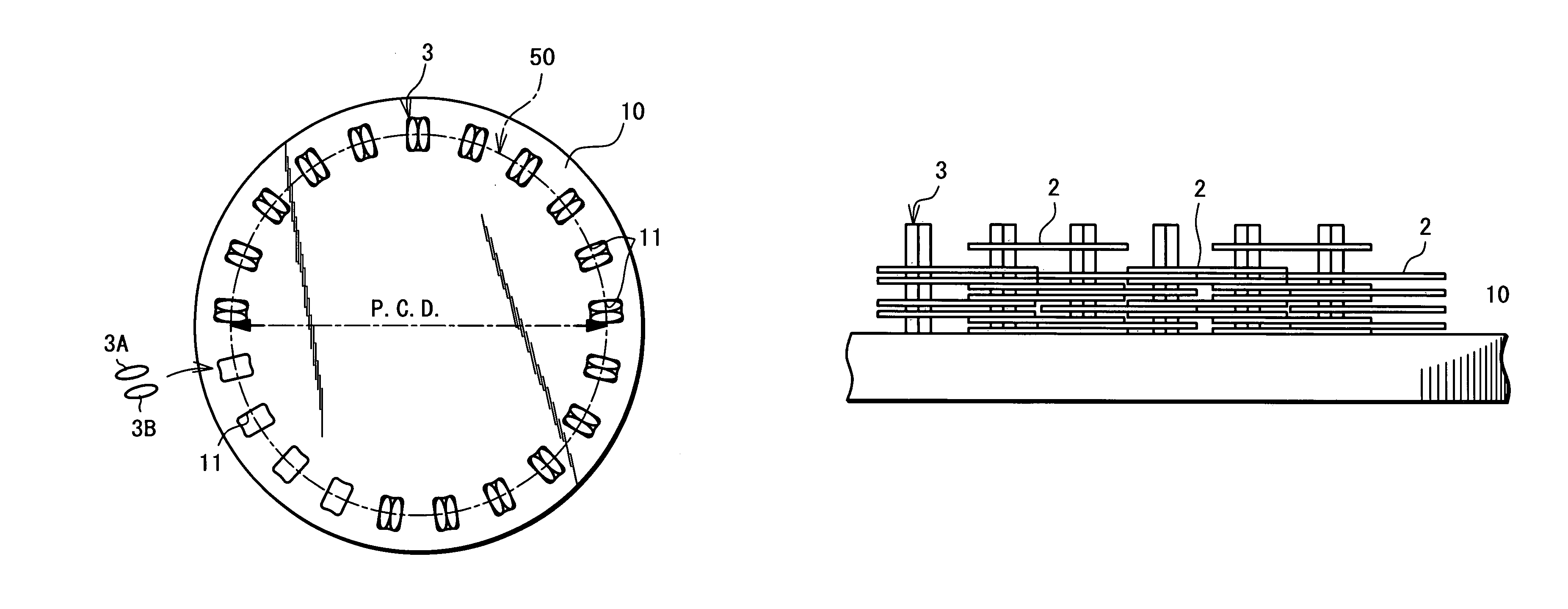
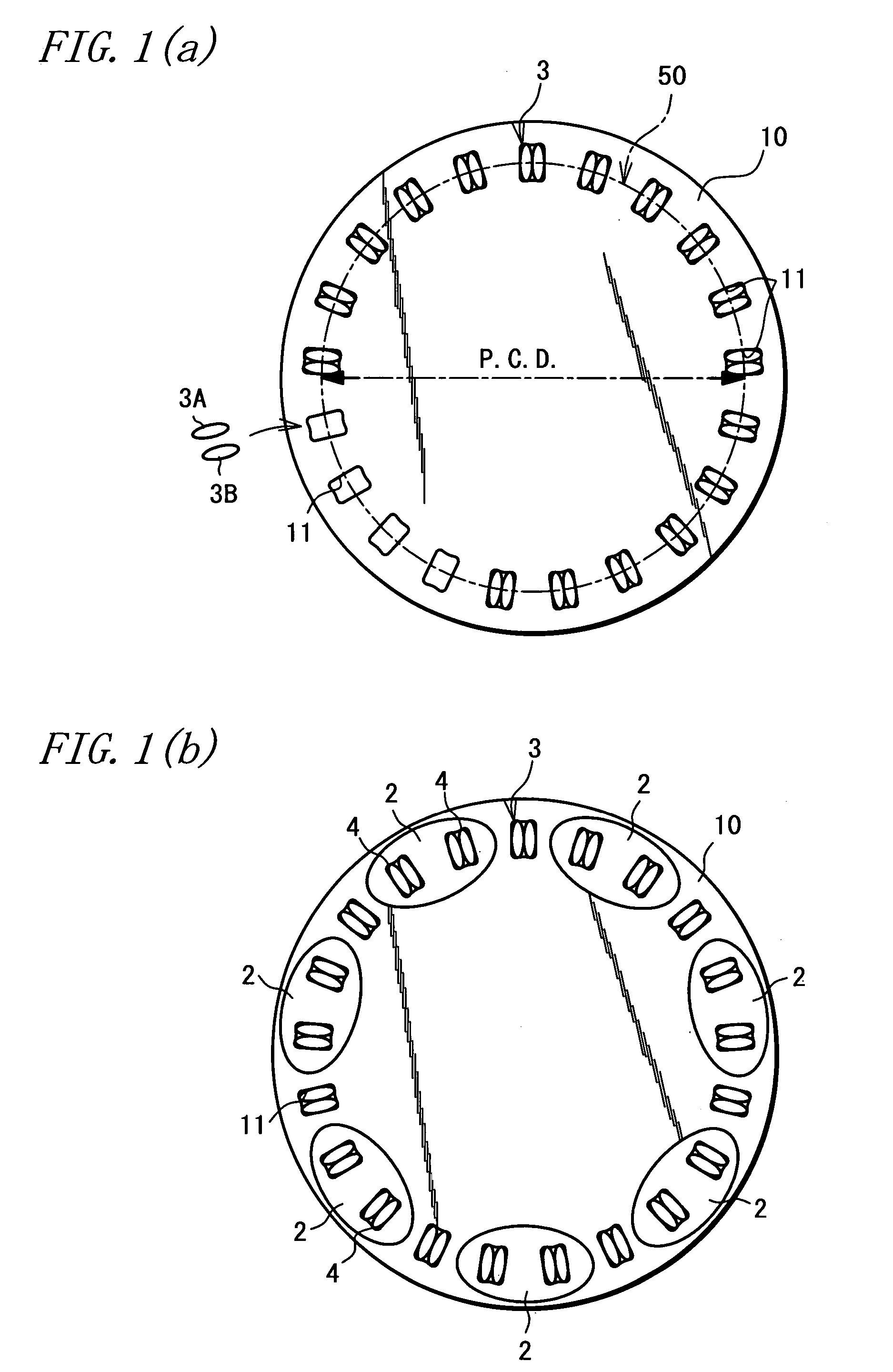
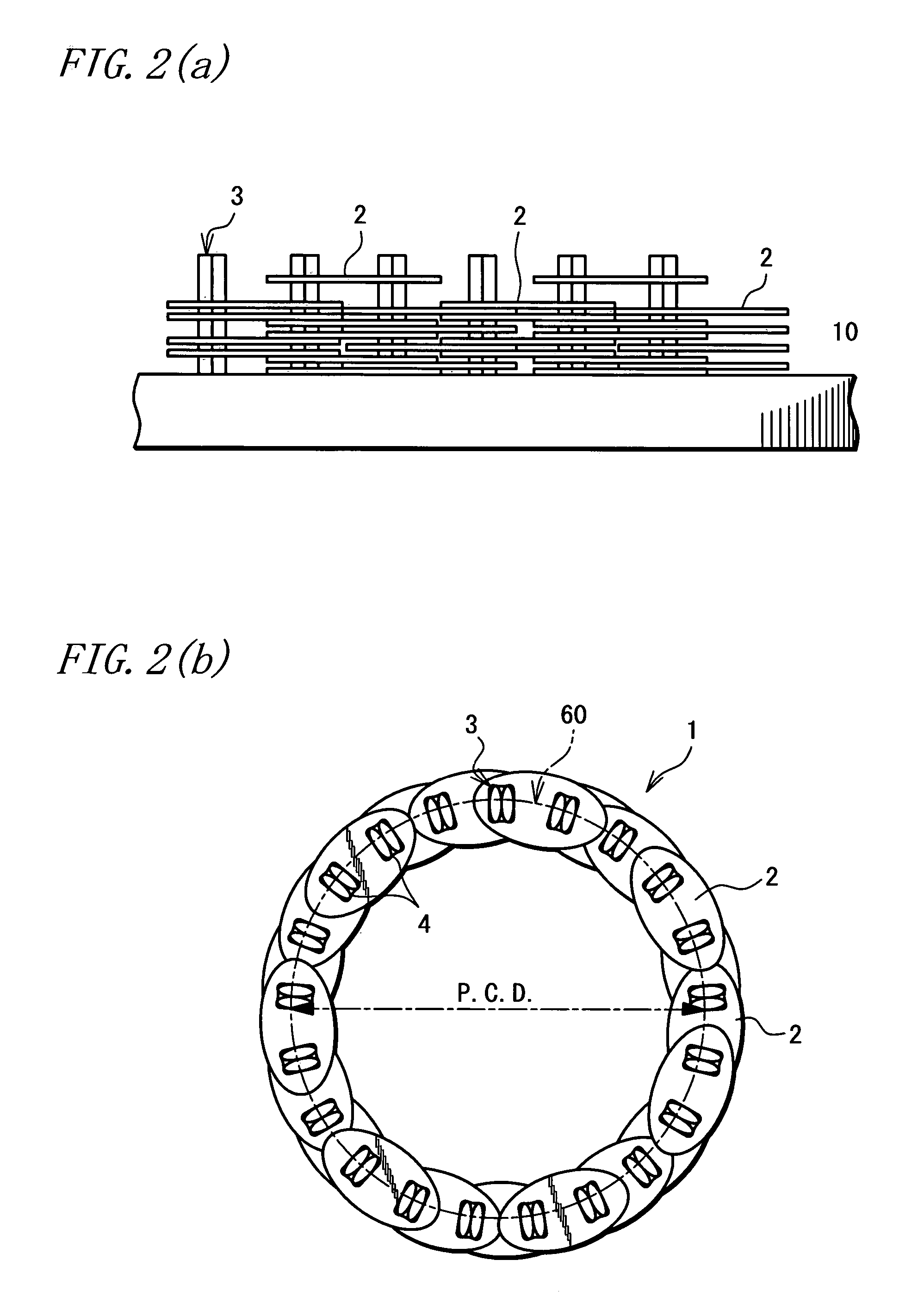
[0023]One embodiment of the invention will hereinbelow be described with reference to the accompanying drawings. As shown in FIG. 2(b), a power transmission chain 1 (hereinafter, referred to as “chain”) according to the embodiment is in an endless form and includes a plurality of link plates 2 formed from a metal (such as a bearing steel); and a plurality of pins 3 formed from a metal (such as a bearing steel) and arranged in pairs for interconnecting these link plates 2. The chain 1 is used, for example, in a continuously variable transmission of an automotive vehicle. The chain is used as entrained between a drive pulley 20 and a driven pulley 30, as shown in FIG. 5.

[0024]The link plate 2 is an elliptical plate material and is formed with two through-holes 4 (a first through-hole, a second through-hole). Each pair of pins 3 are press-inserted through each through-hole 4. The link plates 2 are stacked in layers in a thicknesswise direction of the chain 1 as mutually overlapped in p...


PUM

PropertyMeasurementUnit
lengthaaaaaaaaaa
poweraaaaaaaaaa
groove widthaaaaaaaaaa

Abstract

A method of manufacturing of power transmission chain 1 by interconnecting plural link plates 2 with pins 3. Individual pin pairs 3 are arranged and temporarily fixed to places. The link plates 2 are sequentially stacked in layers by press-fitting respective through-holes 4 of the link plates 2 about the respective pin pairs 3, whereby the link plates 2 are interconnected to form a circular chain (an endless loop). Subsequently, the individual pin pairs 3 are released from the temporarily fixed state. Thus, the manufacture of the power transmission chain 1 is decreased in the number of operation steps, so that the chain may be assembled easily.

Description

TECHNICAL FIELD[0001]The present invention relates to a manufacture method of a power transmission chain for a continuously variable transmission or the like employed by vehicles or the like, and to a pin-retainer jig used in the manufacture method.BACKGROUND ART[0002]The power transmission chain for use in the continuously variable transmission (CVT) for automotive vehicles includes, for example, an endless type which is entrained between a drive pulley on an engine side and a driven pulley on drive wheel side. The continuously variable transmission transmits a great power by way of contact between sheave surfaces of the respective pulleys and end faces of pins of the power transmission chain under boundary lubrication. Furthermore, the continuously variable transmission is adapted to accomplish continuous gear shifting by continuously varying a respective groove width of the pulleys.[0003]The above power transmission chain includes one which is manufactured by a method wherein a p...

Claims


Application Information

Patent Timeline
Patent Type & Authority Patents(United States)
IPC IPC(8): B21L9/06F16G13/06
CPCB21L9/06F16G5/18B21L9/065Y10T29/53826
Inventor FUSE, MASARU
Owner JTEKT CORP
Why Eureka
Try Eureka