Multipoint ignition device

Active Publication Date: 2008-10-28
MIYAMA
View PDF11 Cites 3 Cited by
  • Summary
  • Abstract
  • Description
  • Claims
  • Application Information

AI Technical Summary

Benefits of technology

[0008]According to this invention, the temperatures of all of the electrode pairs can be kept within the appropriate te

Problems solved by technology

, carbon sticks to the electrode pair, and as a result, a secondary voltage leaks, causing pollution such that a spark can no longer fly from the electrode pair. C
Hence, the temperature of certain

Method used


Image

  • Multipoint ignition device
  • Multipoint ignition device
  • Multipoint ignition device

Examples


Embodiment Construction

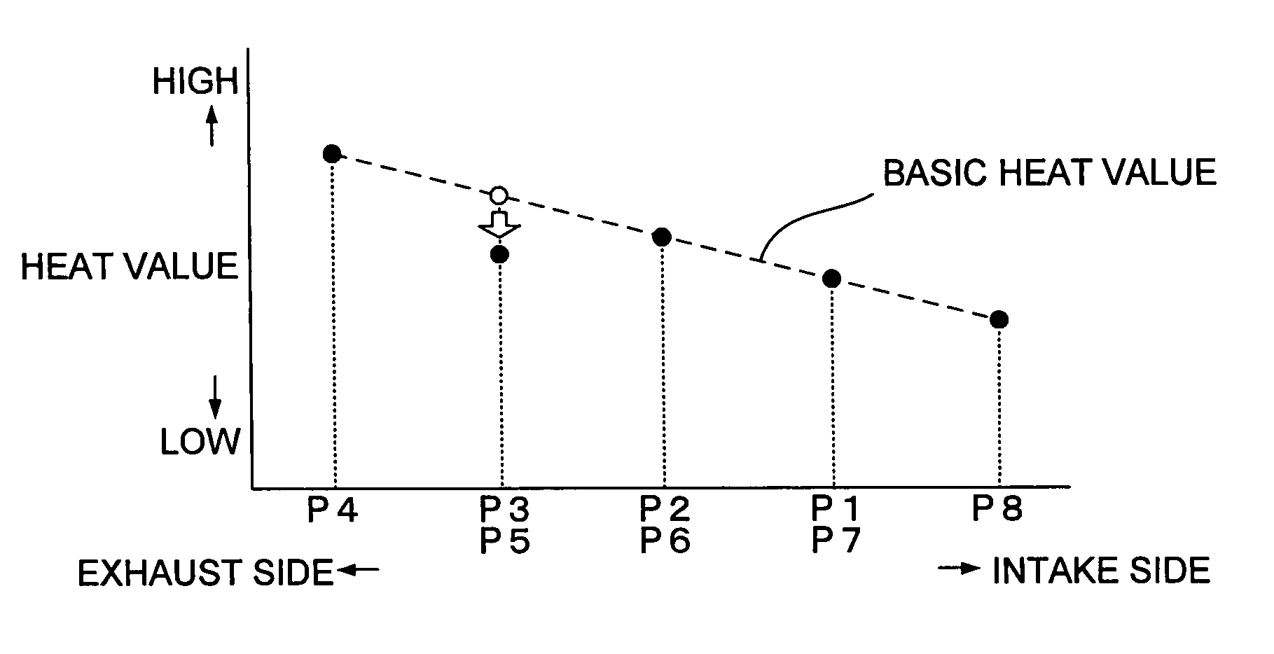
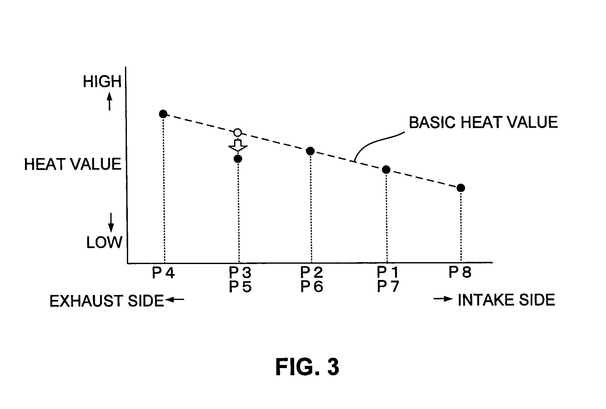
[0013]An embodiment of this invention will be described below with reference to the attached drawings. In the following description, the heat radiation property of an electrode pair is expressed as a “heat value”, similarly to a conventional spark plug. Accordingly, a good heat radiation property is referred to as a “high heat value”, and a poor heat radiation property is referred to as a “low heat value”.

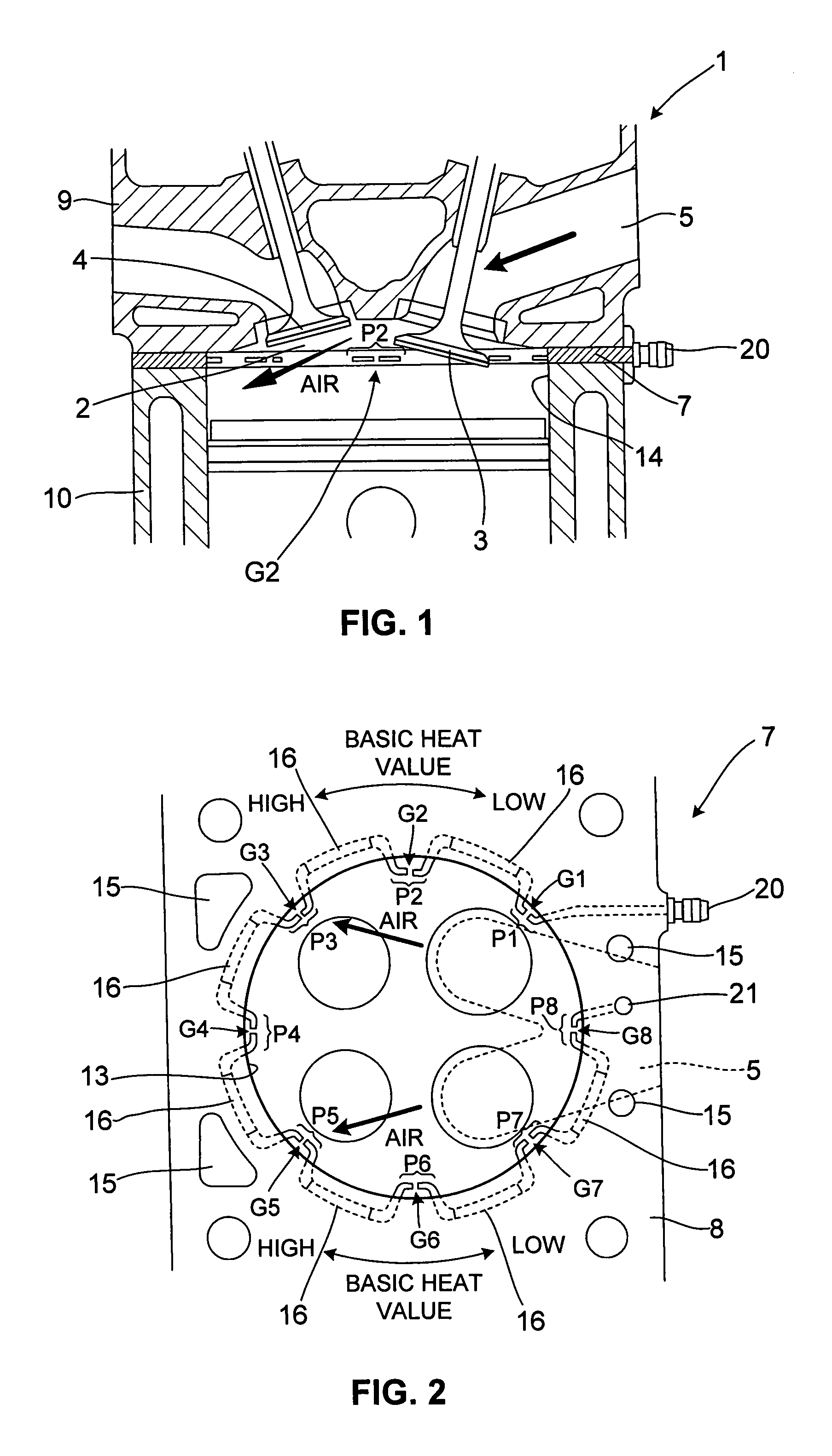
[0014]FIG. 1 shows the schematic constitution of an engine 1 comprising a multipoint ignition device 7 according to this invention. The engine 1 is a four-valve engine having two intake valves 3 and two exhaust valves 4 for a single combustion chamber 2. In this example, the intake valve 3 is mounted in a near-horizontal state (the valve stem is near-vertical), and the majority of fresh air that is introduced into the combustion chamber 2 through an intake port 5 via the intake valve 3 flows to the exhaust side along an upper surface of the combustion chamber 2.

[0015]As shown in FI...


PUM


Abstract

Respective heat values of a plurality of electrode pairs P1 to P8 are set individually such that the temperatures of all of the plurality of electrode pairs (P1 to P8) are kept within an appropriate temperature range in which a temperature no lower than a self-cleaning temperature is set as a lower limit temperature and a lower temperature than a pre-ignition temperature is set as an upper limit temperature.

Description

TECHNICAL FIELD OF THE INVENTION[0001]This invention relates to a multipoint ignition device in which a plurality of ignition gaps are disposed in a single combustion chamber.BACKGROUND OF THE INVENTION[0002]JP2-123281A and JP1-193080A disclose a multipoint ignition device in which a plurality of electrode pairs constituting ignition gaps are disposed around a cylinder opening portion such that an air-fuel mixture in a combustion chamber is ignited from the plurality of ignition gaps.[0003]According to this device, in comparison with a conventional spark plug that performs ignition only from the center of the combustion chamber, combustion of the air-fuel mixture in the peripheral edge portions of the combustion chamber is promoted, enabling improvements in engine output and fuel economy.SUMMARY OF THE INVENTION[0004]When the temperature of the electrode pair is lower than a self-cleaning temperature (between 450° C. and 500° C.), carbon sticks to the electrode pair, and as a result...

Claims


Application Information

Patent Timeline
IPC IPC(8): F02P15/02
CPCF02P15/02F02P15/08
Inventor MINAMI, KATSUAKI
Owner MIYAMA
Why Eureka
Try Eureka