
System and method for providing temperature data from a memory device having a temperature sensor

a memory device and temperature sensor technology, applied in the field of semiconductor memory devices, can solve the problems of cell failure, cell failure, cell failure to meet the requirements of low temperature conditions,

Inactive Publication Date: 2008-10-28
ROUND ROCK RES LLC
View PDF46 Cites 24 Cited by
  • Summary
  • Abstract
  • Description
  • Claims
  • Application Information

AI Technical Summary

Benefits of technology

This solution provides improved temperature resolution and ease of data interpretation, enabling effective temperature monitoring and management to prevent performance degradation and device failure in high-temperature environments.

Problems solved by technology

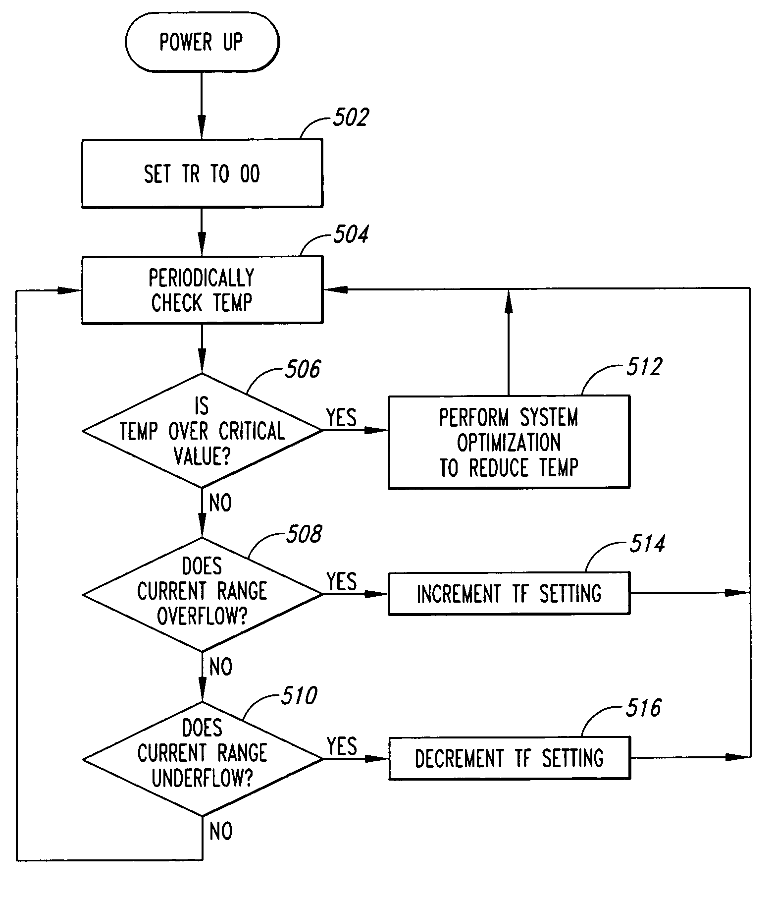
As one can imagine, in such a small and cramped environment, the temperature in which the different devices and circuits operate can be considerable as a result of the heat that is generated as these devices and circuits operate and consume power.
Under some higher temperature conditions, the performance of the various computer devices and circuits begin to degrade.
In severe operating conditions, the temperature may be sufficient to cause some cells, which have acceptable hold characteristics under lower temperature conditions, to fail.
Additionally, transistors included in the circuitry of the SDRAM devices may not be capable of providing the same drive current or switch at the same speed under higher temperature conditions, causing SDRAM device performance to degrade.
Generating less heat generally results in lower operating temperatures.
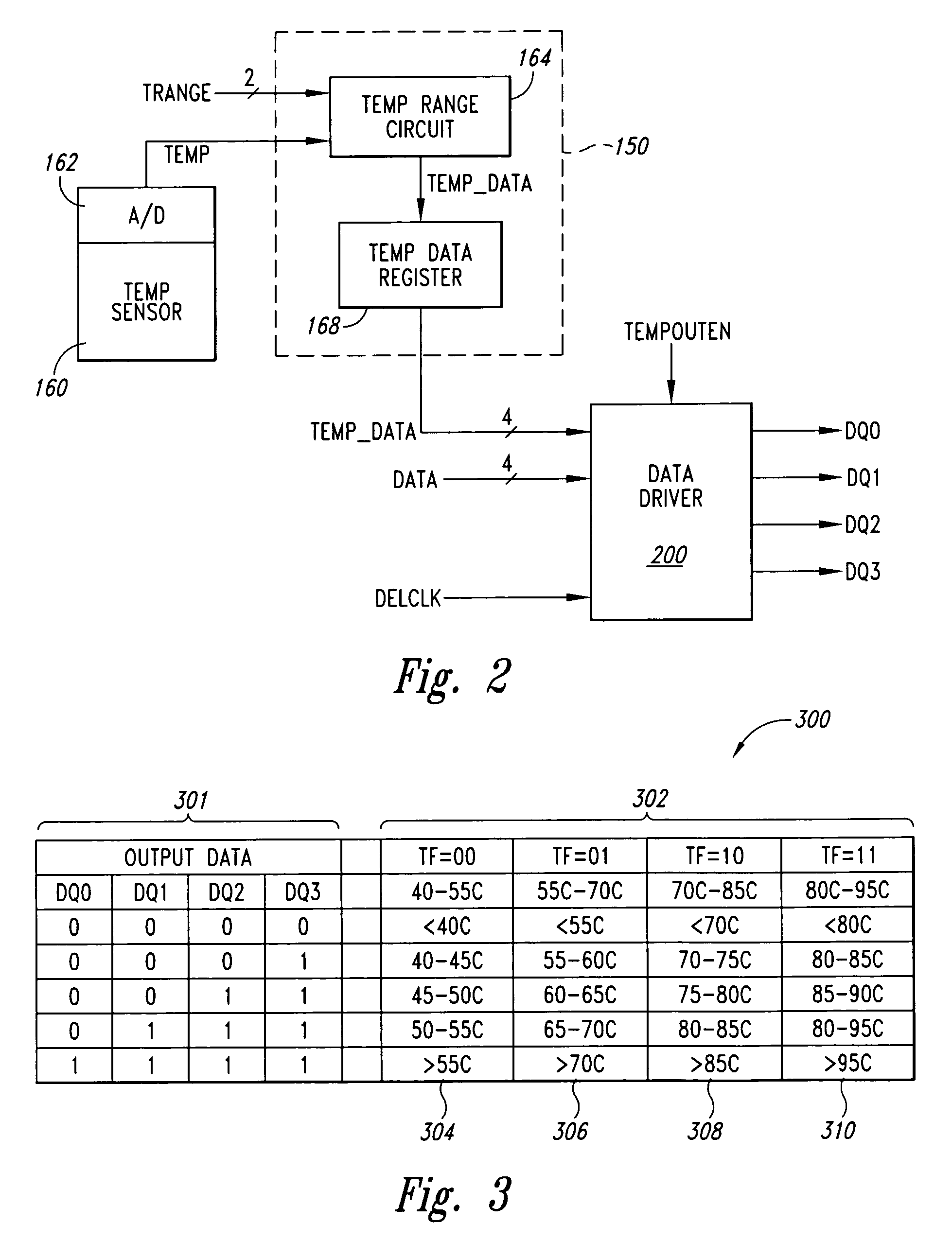
Although the output data of the memory device can be easily interpreted to provide an indication of the measured temperature relative of a single temperature threshold, this approach may be unacceptable where data representing greater temperature resolution is desired.
Thus, where even greater temperature resolution is desired, the previously described approach will be unacceptable.
Additionally, programming the temperature thresholds adds complexity to the set-up and operation of memory devices having this feature.
Additionally, sequentially outputting the data word can interfere with normal read and write operations that occur immediately following the output of the temperature data.

Method used


Image

  • System and method for providing temperature data from a memory device having a temperature sensor
  • System and method for providing temperature data from a memory device having a temperature sensor
  • System and method for providing temperature data from a memory device having a temperature sensor

Examples


Embodiment Construction

[0018]Embodiments of the present invention are directed to a temperature data output circuit and method for a semiconductor device having an integrated temperature sensor. Certain details are set forth below to provide a sufficient understanding of the invention. However, it will be clear to one skilled in the art that the invention may be practiced without these particular details. Moreover, the particular embodiments of the present invention described herein are provided by way of example and should not be used to limit the scope of the invention to these particular embodiments. In other instances, well-known circuits, control signals, timing protocols, and software operations have not been shown in detail in order to avoid unnecessarily obscuring the invention.

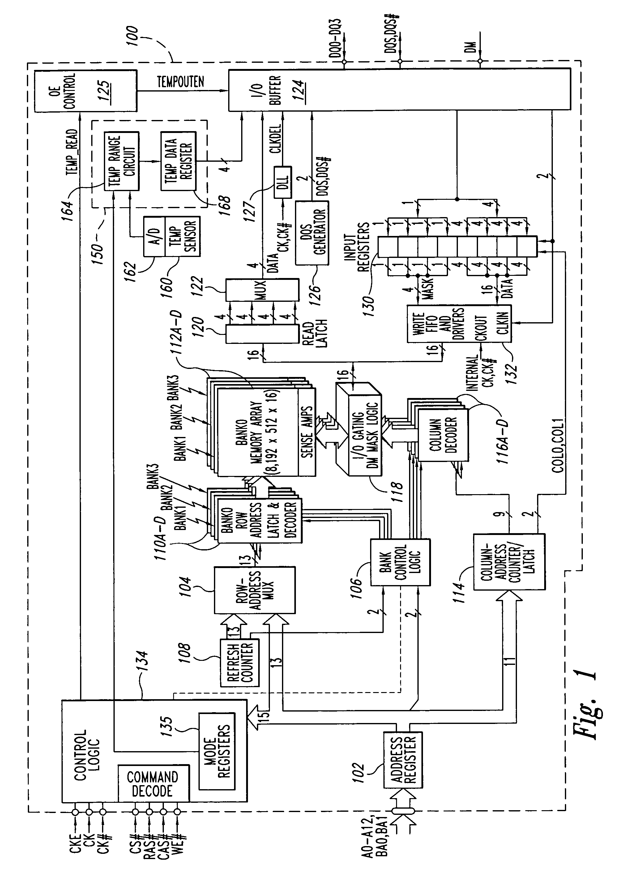
[0019]FIG. 1 illustrates a memory device in which a temperature data output circuit 150 according to an embodiment of the present invention is implemented. Application of the principles described herein, however, is not lim...


PUM

PropertyMeasurementUnit
clock frequenciesaaaaaaaaaa
temperatureaaaaaaaaaa

Abstract

A circuit and method for providing temperature data indicative of a temperature measured by a temperature sensor. The circuit is coupled to the temperature sensor and configured to identify for a coarse temperature range one of a plurality of fine temperature ranges corresponding to the temperature measured by the temperature sensor and generate temperature data that is provided on an asynchronous output data path.

Description

TECHNICAL FIELD[0001]The invention relates generally to semiconductor memory devices, and more specifically, to memory devices having an integrated temperature sensor for measuring a temperature related to the memory device and providing output data representative of the measured temperature.BACKGROUND OF THE INVENTION[0002]A common semiconductor device is a dynamic random access memory (“DRAM”) device. The DRAM device is typically used for storing data, for example, in a computer system. Current DRAM devices are designed to operate synchronously in accordance with a system clock, which can have clock frequencies greater than 600 MHz. These devices are referred to as synchronous DRAM (“SDRAM”) devices. SDRAM devices can be used in a variety of applications, many of which are in compact environments with adjacent electronics devices in relatively close proximity to the SDRAM devices. A common example of such an environment is a conventional portable laptop computer, where SDRAM devic...

Claims


Application Information

Patent Timeline
Patent Type & Authority Patents(United States)
IPC IPC(8): G01K7/00
CPCG01K7/00G01K2219/00G01K1/022G01K7/01G01K7/24
Inventor JANZEN, JEFF W.WRIGHT, JEFFREY P.FARRELL, TODD D.
Owner ROUND ROCK RES LLC
Learn More