Orthodontic bracket and clip release tool
a technology for orthodontic brackets and tools, applied in dental tools, dental surgery, medical science, etc., can solve the problems of clip deformation, clip deformation, and often deformation of clips, so as to prevent clip tuning up and deformation
- Summary
- Abstract
- Description
- Claims
- Application Information
AI Technical Summary
Benefits of technology
Problems solved by technology
Method used
Image
Examples
first embodiment
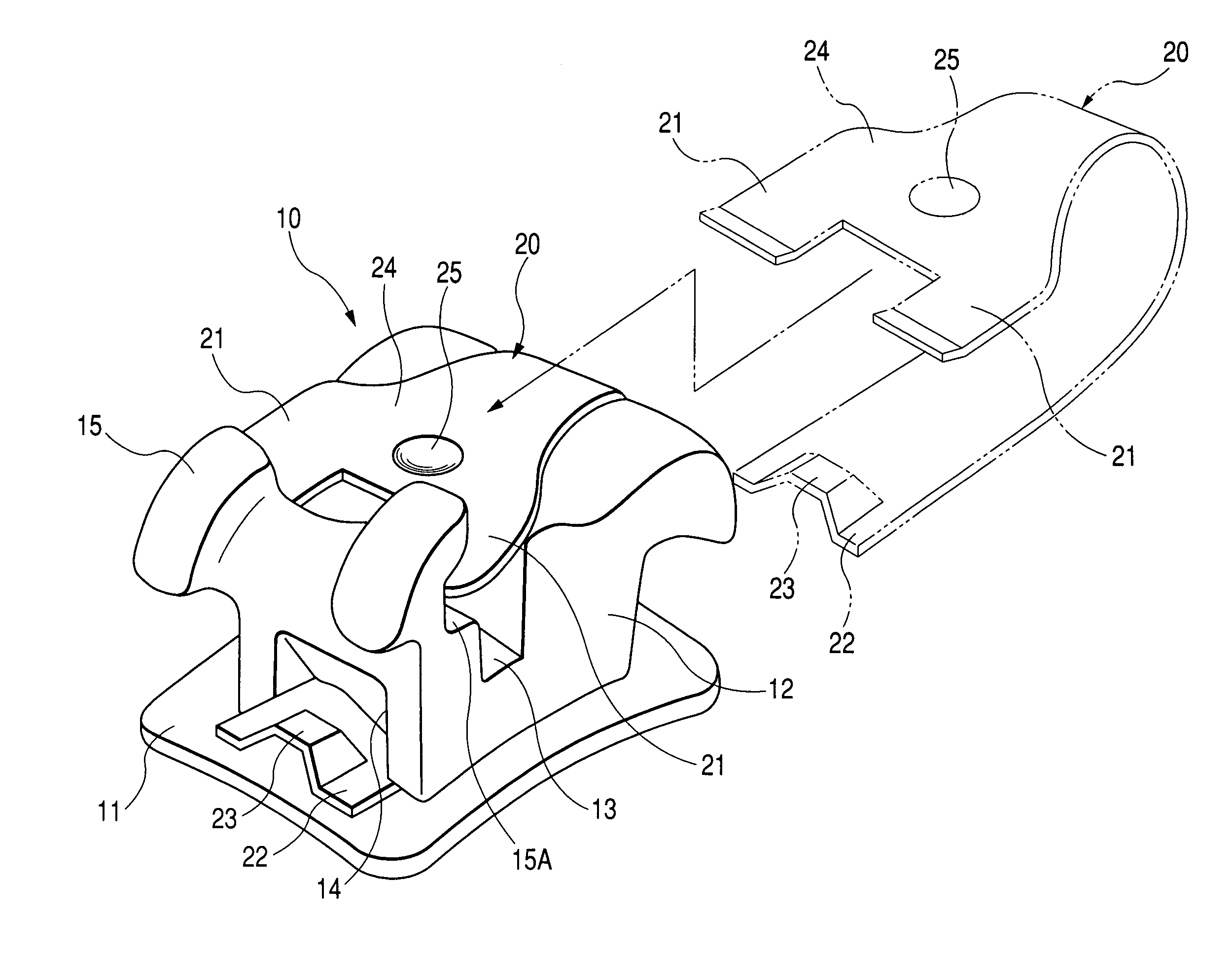
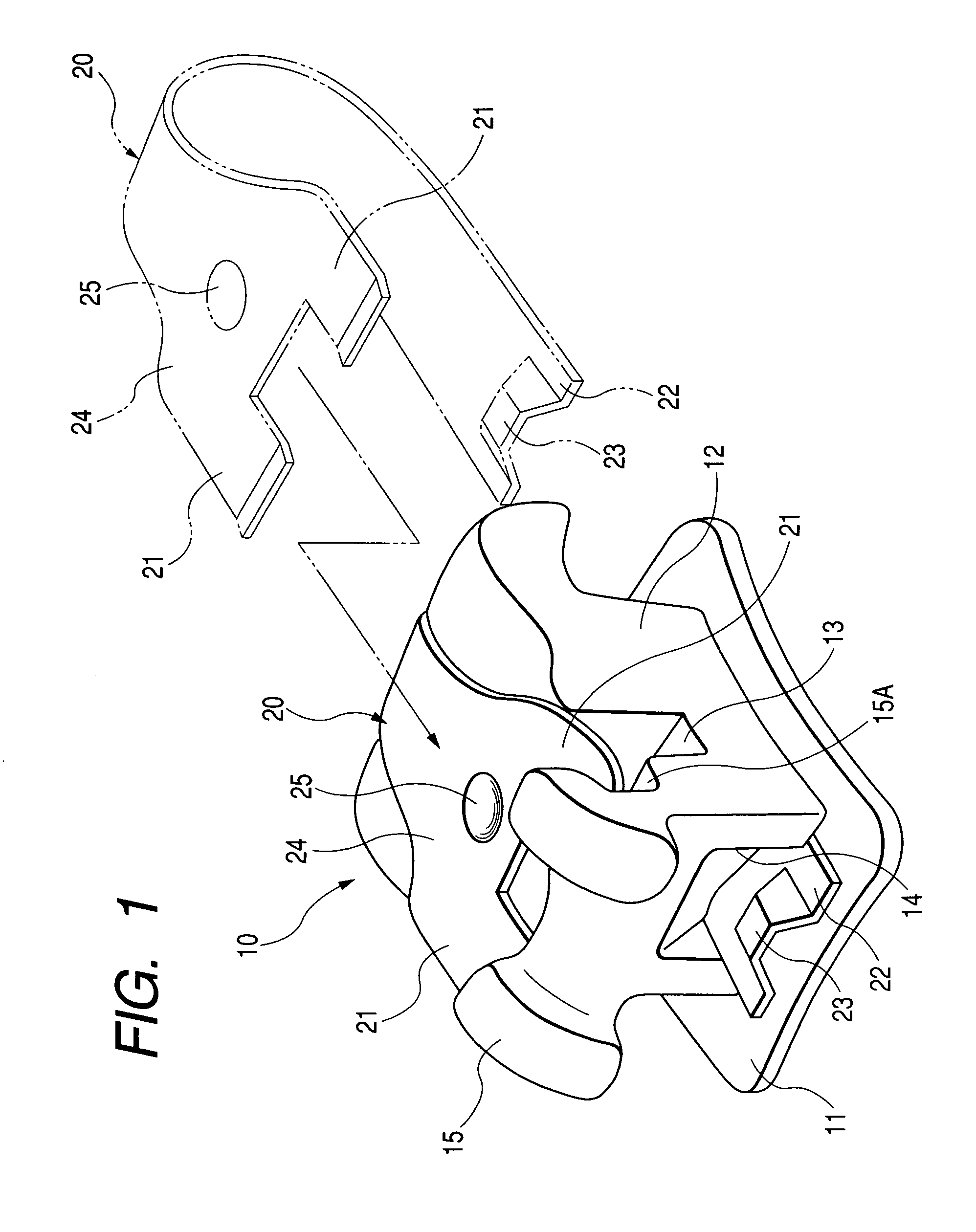
[0076]As shown in FIG. 1, an orthodontic bracket 10 as the invention comprises a base 11, a bracket main body 12, an arch wire slot 13, a guide portion 14, and a substantially belt-like clip 20. The base 11 is firmly attachable directly or indirectly to teeth surfaces. The bracket main body 12 is equipped on one side of the base 11. The arch wire slot 13 is shaped in groove in the bracket main body 12. The guide portion 14 is formed in at least one of the bracket main body and the base, and along a tooth axial direction crossing with the arch wire slot 13. The substantially belt-like clip 20 is guided by the guide portion 14.
[0077]The arch wire slot 13 is formed along the mesiodistal direction of the bracket main body 12.
[0078]In the orthodontic bracket 10, the clip 20 is curved substantially in U-shape as covering at least one part of an opposite side to the base in the arch wire slot 13. A pair of catching end portions 21 are provided at an upper end part along length of the clip ...
third embodiment
[0124]Next, a third embodiment will be referred to.
[0125]As shown in FIG. 12, a clip 50 as the third embodiment of the invention is different from the clip 20 of the first embodiment only in that the clip 50 has, as the recess portion, a cut-and-rising portion 51 rising in a direction separating from the bracket main body 12 (see FIG. 1) along the thickness, and other structures are the same as those of the first embodiment.
[0126]The cut-and-rising portion 51 is provided substantially in a half-spherical dome shape at an end part 52 of the clip 50.
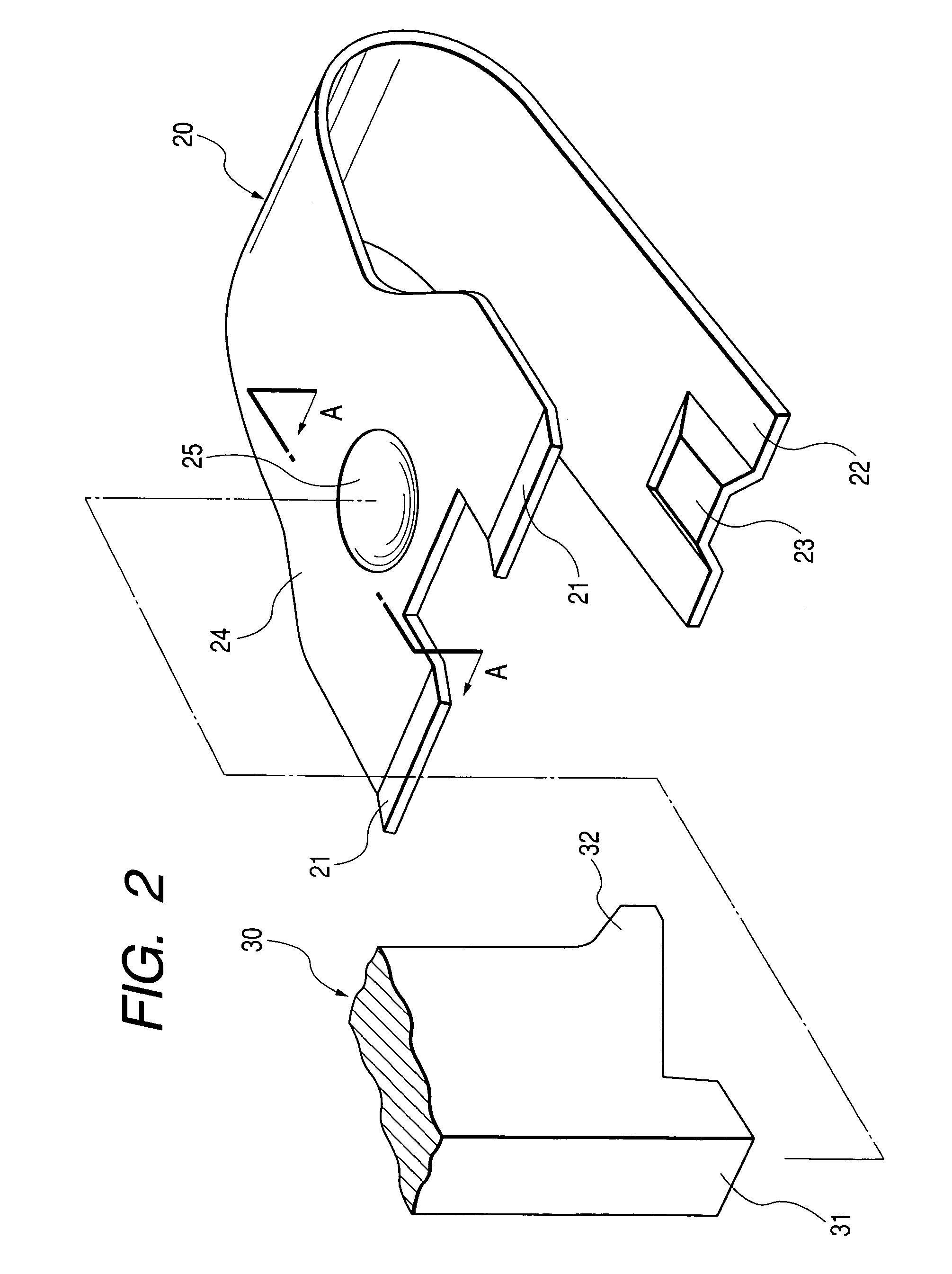
[0127]If the clip release tool 30 is moved under a condition of contacting the heel portion 31 (see FIG. 2) to the cut-and-rising portion 51, the clip 50 can be released together with the clip release tool 30.
[0128]In the clip 50 of the third embodiment, the same effect as that of the clip 20 of the first embodiment can be also obtained.
fourth embodiment
[0129]Next, a fourth embodiment will be referred to.
[0130]As shown in FIG. 13, a clip 60 as the fourth embodiment of the invention is different from the clip 20 of the first embodiment only in that the clip 60 has, as the recess portion, a cut-and-rising portion 61 raising in a direction separating from the bracket main body 12 (see FIG. 1) along the thickness, and other structures are the same as those of the first embodiment.
[0131]The cut-and-rising portion 61 is provided substantially in a half-spherical dome shape at an end part 62 of the clip 60, and a cutout portion 64 substantially in V-shape is provided in a flat end part 63 of the cut-and-rising portion 61.
[0132]If the clip release tool 30 is moved under a condition of contacting the heel portion 31 (see FIG. 2) to the cut-and-rising portion 61, the clip 60 can be released together with the clip release tool 30.
[0133]In this case, since the substantially V-shaped cutout 64 is provided in the flat end part 63 of the cut-and-...
PUM
 Abstract
Description
Claims
Application Information
 - R&D
- Intellectual Property
- Life Sciences
- Materials
- Tech Scout
- Unparalleled Data Quality
- Higher Quality Content
- 60% Fewer Hallucinations
Browse by: Latest US Patents, China's latest patents, Technical Efficacy Thesaurus, Application Domain, Technology Topic, Popular Technical Reports.
© 2025 PatSnap. All rights reserved.Legal|Privacy policy|Modern Slavery Act Transparency Statement|Sitemap|About US| Contact US: help@patsnap.com


