Therapeutic cushion

a cushion and cushion technology, applied in the field of cushions, can solve the problems of pressure sores, nerve damage, nerve damage, etc., and achieve the effects of reducing pain, discomfort, and/or formation of sores

Active Publication Date: 2008-11-04
JACKSON III AVERY M
View PDF21 Cites 27 Cited by
  • Summary
  • Abstract
  • Description
  • Claims
  • Application Information

AI Technical Summary

Benefits of technology

[0017]The present invention is a therapeutic support cushion that has a plurality of chambers or sections with means for temporarily removing or reducing the support provided by each section to thereby cyclically and temporarily relieve pressure on different areas of a person's anatomy, thus improving comfort and preventing the formation of pressure sores or other adverse effects on tissue contacted and supported by the cushion. In particular, the present invention is directed to a cushion for supporting the face of a person lying prone during surgery.

Problems solved by technology

Prolonged immobilization of a person, with the resultant constant pressure on parts of the body, can, at a minimum, lead to discomfort, but can also lead to more serious consequences such as the formation of pressure sores, decubitus ulcers, nerve damage, and / or other problems.
During long surgical procedures, for example, an anesthetized patient cannot move voluntarily, and pressure sores or other tissue damage can result on parts of the patient's body that rest on supporting surfaces.
The resulting discomfort and / or formation of sores and the like can be especially acute in those persons who have lost weight and / or muscle mass, since the buttocks (gluteus maximus) may not provide sufficient padding to prevent concentration of pressure on, for example, tissue overlying the coccyx or ischial tuberosity.
Although U.S. Pat. No. 5,412,822 discloses a cushion that can be placed in a wheelchair for a patient to sit on, and therefore undoubtedly would increase comfort, there is no suggestion of any means for cyclically varying the extent of support provided by different areas of the cushion, or of using the power source of the wheelchair itself as a means for inflating and deflating the cushion.

Method used


Image

  • Therapeutic cushion
  • Therapeutic cushion
  • Therapeutic cushion

Examples


first embodiment

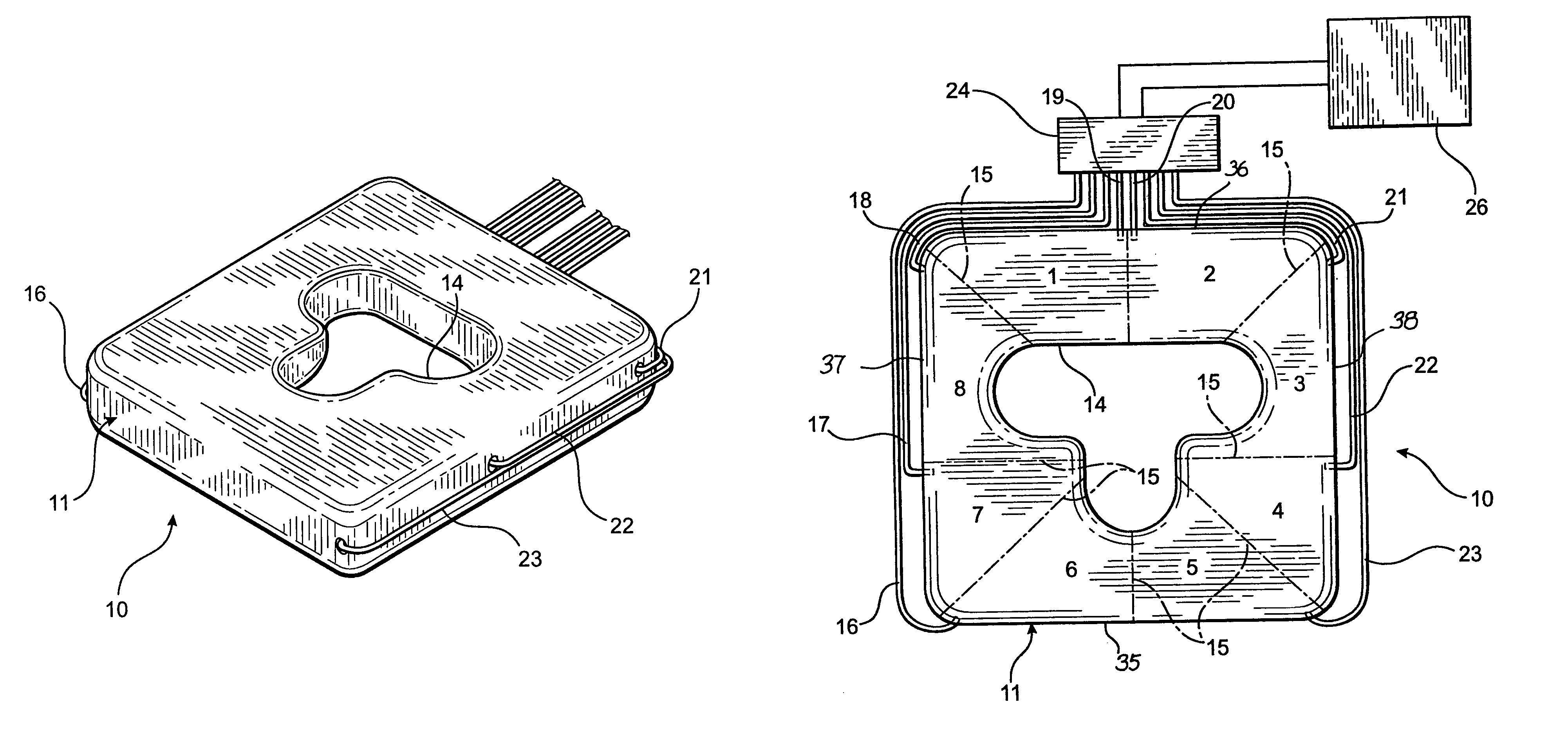
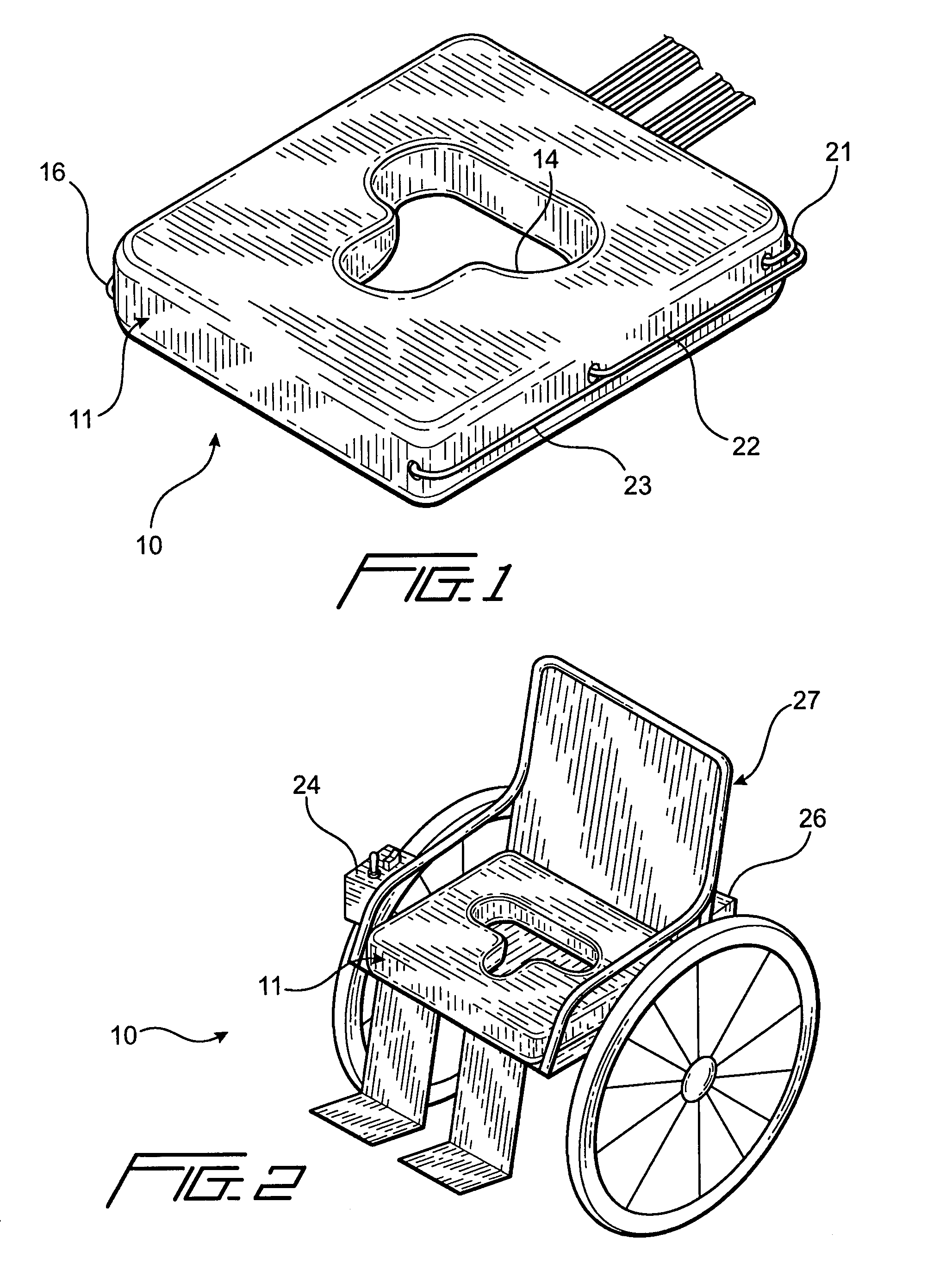
[0025]FIG. 1 is a top perspective view of a cushion according to the invention, wherein the cushion is used as a seat cushion.

[0026]FIG. 2 is a somewhat schematic top perspective view of the cushion of FIG. 1 positioned on a wheelchair.

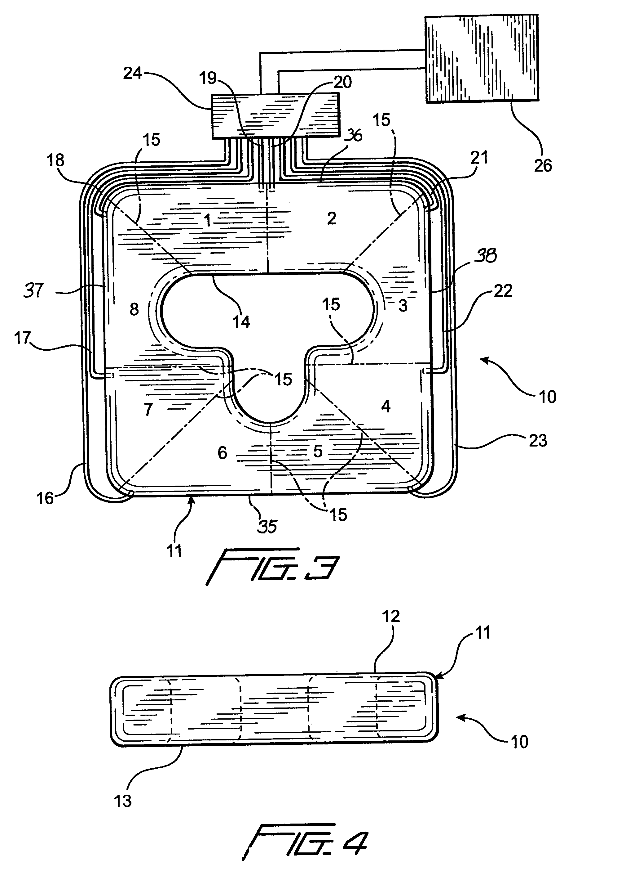
[0027]FIG. 3 is a top plan view of the cushion of FIG. 1, with some of the control means attached.

[0028]FIG. 4 is a side view in elevation of the cushion of FIG. 1.

second embodiment

[0029]FIG. 5 is a top plan view of cushion according to the invention.

[0030]FIG. 6 is a transverse sectional view of the cushion of FIG. 5, taken along line 6-6 in FIG. 5.

[0031]FIG. 7 is a transverse sectional view of the cushion of FIG. 5, taken along line 7-7 in FIG. 5.

[0032]FIG. 8 is a transverse sectional view of the cushion of FIG. 5, taken along line 8-8 in FIG. 5.

[0033]FIG. 9 is a top plan view of the cushion of FIG. 5, with the control means attached.

[0034]FIG. 10 is a top plan view of a facial support cushion according to another embodiment of the invention.

[0035]FIG. 11 is a transverse sectional view of the cushion of FIG. 10, taken along line 11-11 in FIG. 10.

[0036]FIG. 12 is a transverse sectional view of the cushion of FIG. 10, taken along line 12-12 in FIG. 10.

[0037]FIG. 13 is a somewhat schematic sectional view of the cushion, taken along line 13-13 in FIG. 10, and showing the relationship between the cushion and the face of a person using the cushion.

[0038]FIG. 14 is...


PUM


Abstract

A facial support cushion for supporting the face of a person lying in a prone position, wherein the cushion is an annular, generally torus shaped body having a hollow interior with a plurality of generally radially extending partitions extending across the interior of the body, dividing it into a plurality of individual chambers spaced sequentially around the body. Apparatus is connected with the chambers to sequentially expand and contract them in an alternating pattern so that some of the chambers are expanded to contact and support the face while other chambers are contracted to relieve the pressure exerted against the face by the other chambers, whereby the formation of pressure sores and other deleterious effects are avoided by periodically and temporarily relieving pressure exerted by the chambers against different areas of the face.

Description

RELATED APPLICATIONS[0001]This application is a continuation-in-part of prior application Ser. No. 11 / 208,677, filed Aug. 22, 2005, now U.S. Pat. No. 7,225,486 which is a continuation-in-part of application Ser. No. 11 / 032,371, filed Jan. 10, 2005 now abandoned.FIELD OF THE INVENTION[0002]This invention relates generally to cushions for supporting parts of the human anatomy. In particular, the invention is a therapeutic cushion for supporting parts of the anatomy of persons remaining in an immobile position for prolonged periods of time, with means to periodically relieve the pressure exerted on different areas of the anatomy by the cushion, thereby improving blood circulation and comfort, stimulating muscles, and preventing or reducing the formation of sores and other harmful effects of prolonged immobility.DESCRIPTION OF THE PRIOR ART[0003]Prolonged immobilization of a person, with the resultant constant pressure on parts of the body, can, at a minimum, lead to discomfort, but can...

Claims


Application Information

Patent Timeline
Patent Type & Authority Patents(United States)
IPC IPC(8): A47C20/00A47C16/00A47C20/02B68G5/00
CPCA47G9/1027A61G5/1043A61G13/12A61G13/121A61G13/1245A61G2005/1045A61G2013/0054A61G2200/325A61G2200/34A61G5/1045A61G13/0054
Inventor JACKSON, III, AVERY M.
Owner JACKSON III AVERY M
Why Eureka
Try Eureka