Method for fabricating horn antenna

a technology of antenna array and antenna plate, which is applied in the field of antenna plate, can solve the problems of exacerbated problems associated with the fabrication of antenna plate array, and efficient radiator in the plane of the board

Inactive Publication Date: 2008-11-04
LOCKHEED MARTIN CORP
View PDF7 Cites 39 Cited by
  • Summary
  • Abstract
  • Description
  • Claims
  • Application Information

AI Technical Summary

Problems solved by technology

The problems associated with the fabrication of antenna arrays is exacerbated by the need which often occurs for the ability to radiate dual polarizations, which is to say the ability to selectively radiate or receive mutually orthogonal polarizations of electromagnetic energy, often termed Electric (E) and Magnetic (M) or Vertical “V” and Horizontal “H” polarizations, regardless of the actual orientations of the fields of the polarizations.
Such a printed board has a significant dimension only in one plane, so can only be an efficient radiator in the plane of the board.
This may allow some play at the radiating ends of the horns as assembled into the array, which in turn may tend produce imperfect results.

Method used


Image

  • Method for fabricating horn antenna
  • Method for fabricating horn antenna
  • Method for fabricating horn antenna

Examples


Embodiment Construction

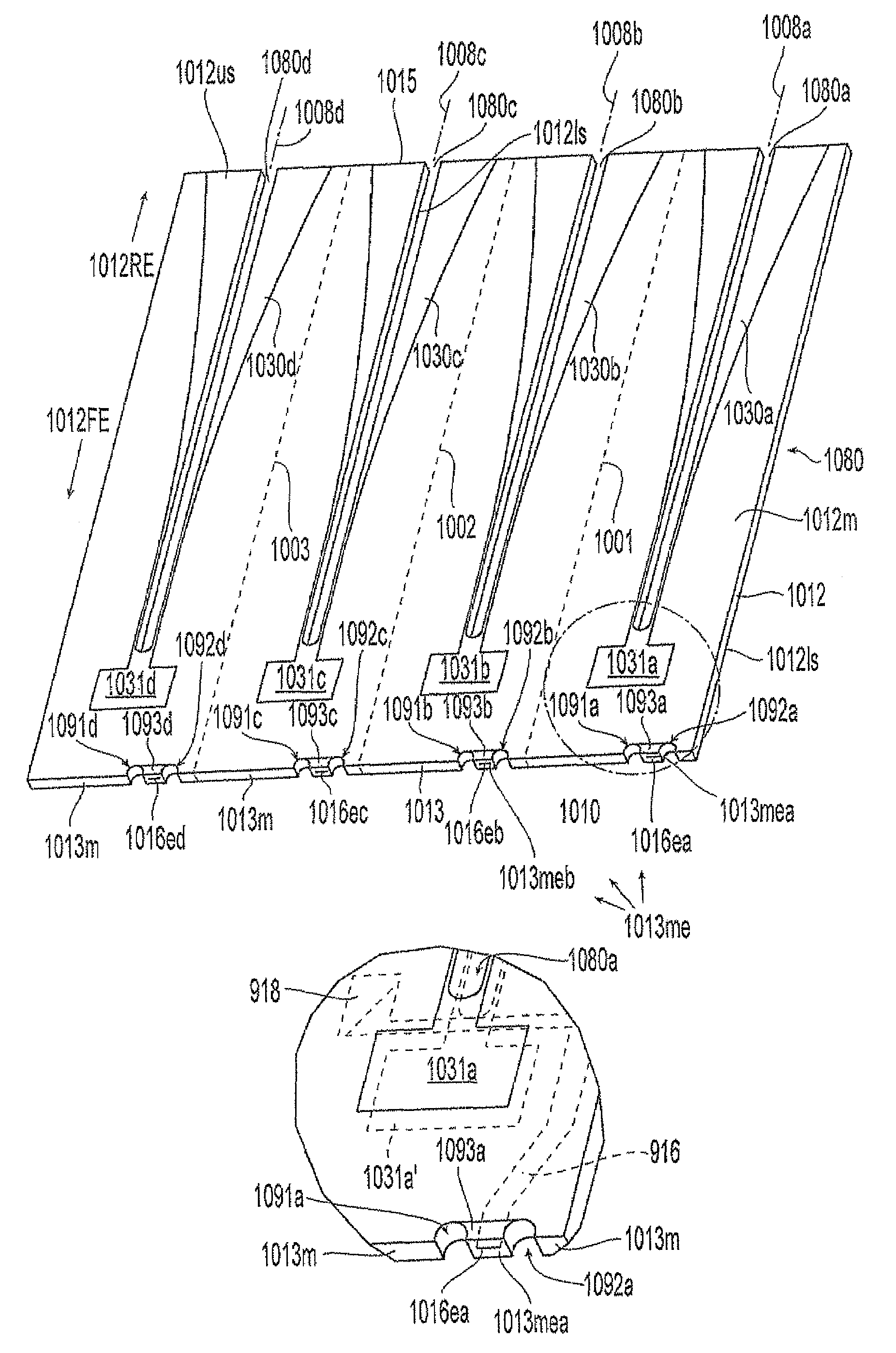
[0047]FIG. 9 illustrates a portion of juxtaposed, preferably joined, dielectric boards designated 912 and 914. The plane of the juxtaposition is designated 911. These boards are made generally by prior art methods. The illustrated portion of the structure 910 is near the feed end 910FE. The joined boards 912 and 914 together define a feed-end edge designated 913. The near or upper surface 912us of the joined boards 912, 914 is covered with a pattern of electrically conductive material 912m, which may be a metallization, defining a slot antenna 930 (only a portion of which is visible) and its matching cavity 931. A dash line region illustrates the location and path of the feed structure 918 and the feed strip conductor 916, and also of the feed end 916e of the strip conductor. According to an aspect of the invention, the metallization includes a portion designated 913m, which extends onto the edges 913 of the juxtaposed or joined dielectric boards 912, 914. A portion 913me of metalli...


PUM

PropertyMeasurementUnit
electrically conductiveaaaaaaaaaa
dielectricaaaaaaaaaa
lengthaaaaaaaaaa

Abstract

A method for making a horn antenna array includes the steps of making planar boards with surface conductor or metallization defining a plurality of side-by-side horns, and with horn feed conductors extending to an edge of the boards. The edges of the board are metallized in a pattern to define feed pads in contact with the feed conductors. Slots are cut in the boards on the axes of the horns so that two orthogonal boards can be joined together for “radiation” in mutually orthogonal planes. A surface-conducive dielectric support defines surface pads in a pattern that matches the pattern of feed pads in a set of joined boards, and through vias connect from the surface pads to lower layers, which may include a beamformer, for making individual connections to the horns.

Description

FIELD OF THE INVENTION[0001]This invention relates to antennas and to methods for making antennas and arrays of such elements.BACKGROUND OF THE INVENTION[0002]Those skilled in the arts of antenna arrays and beamformers know that antennas are transducers which transduce electromagnetic energy between unguided- and guided-wave forms. More particularly, the unguided form of electromagnetic energy is that propagating in “free space,” while guided electromagnetic energy follows a defined path established by a “transmission line” of some sort. Transmission lines include coaxial cables, rectangular and circular conductive waveguides, dielectric paths, and the like. Antennas are totally reciprocal devices, which have the same beam characteristics in both transmission and reception modes. For historic reasons, the guided-wave port of an antenna is termed a “feed” port, regardless of whether the antenna operates in transmission or reception. The beam characteristics of an antenna are establis...

Claims


Application Information

Patent Timeline
Patent Type & Authority Patents(United States)
IPC IPC(8): H01P11/00H01Q13/00H01Q17/00
CPCH01Q13/0283H01Q13/085H01Q21/0087H01Q21/064Y10T29/49128Y10T29/49018Y10T29/49126Y10T29/49016
Inventor WARNING, FRED W.
Owner LOCKHEED MARTIN CORP
Why Eureka
Try Eureka