Four-wheeled vehicle

a four-wheeled vehicle technology, applied in the field of vehicle improvement, can solve the problems of driver and passenger getting on or off the vehicle with difficulty or trouble, not designed to take into account the protection of the driver, and the vehicle's center of gravity is positioned higher

Inactive Publication Date: 2008-11-04
HONDA MOTOR CO LTD
View PDF37 Cites 32 Cited by
  • Summary
  • Abstract
  • Description
  • Claims
  • Application Information

AI Technical Summary

Benefits of technology

[0057]The thus arranged vehicle can be parked in a space having the same length as a motorcycle. According...

Problems solved by technology

With this arrangement, the vehicle undesirably has its center of gravity positioned higher.
This is disadvantageous in that the driver and passenger get on or off the vehicle wit...

Method used


Image

  • Four-wheeled vehicle
  • Four-wheeled vehicle
  • Four-wheeled vehicle

Examples


first embodiment

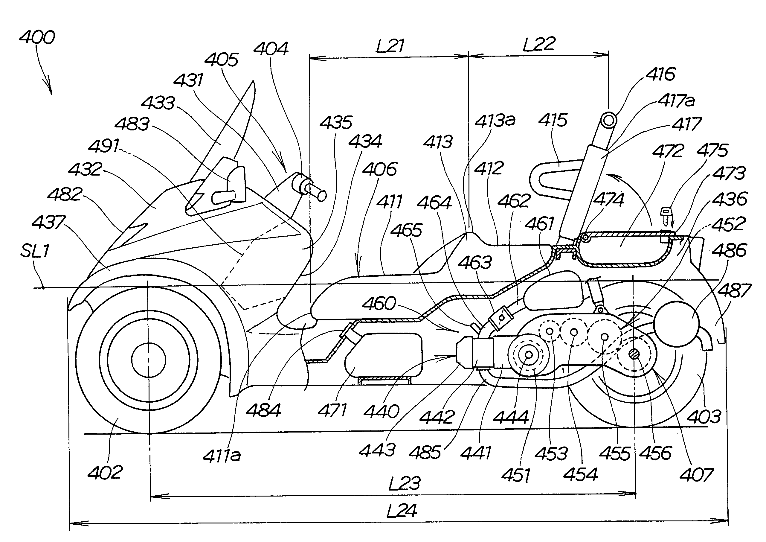
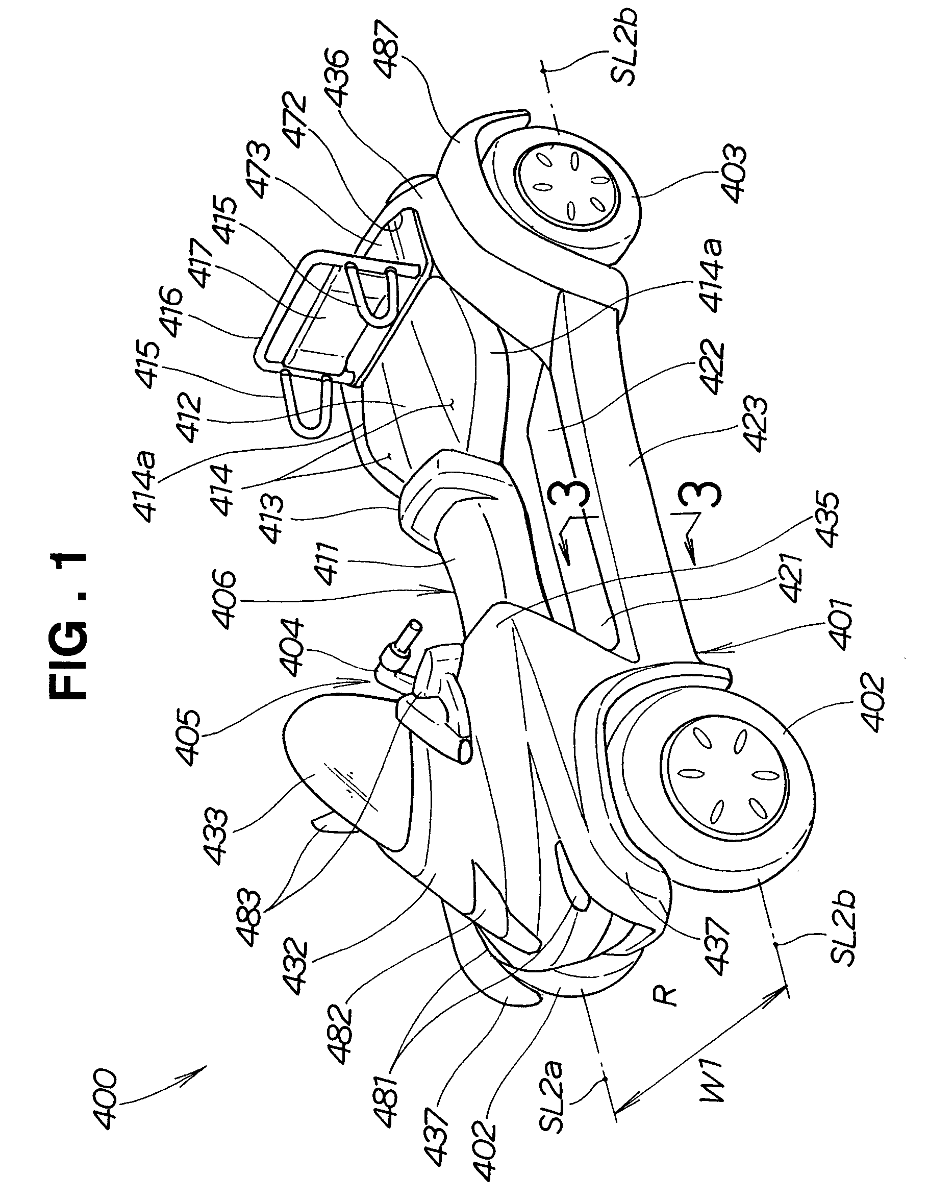
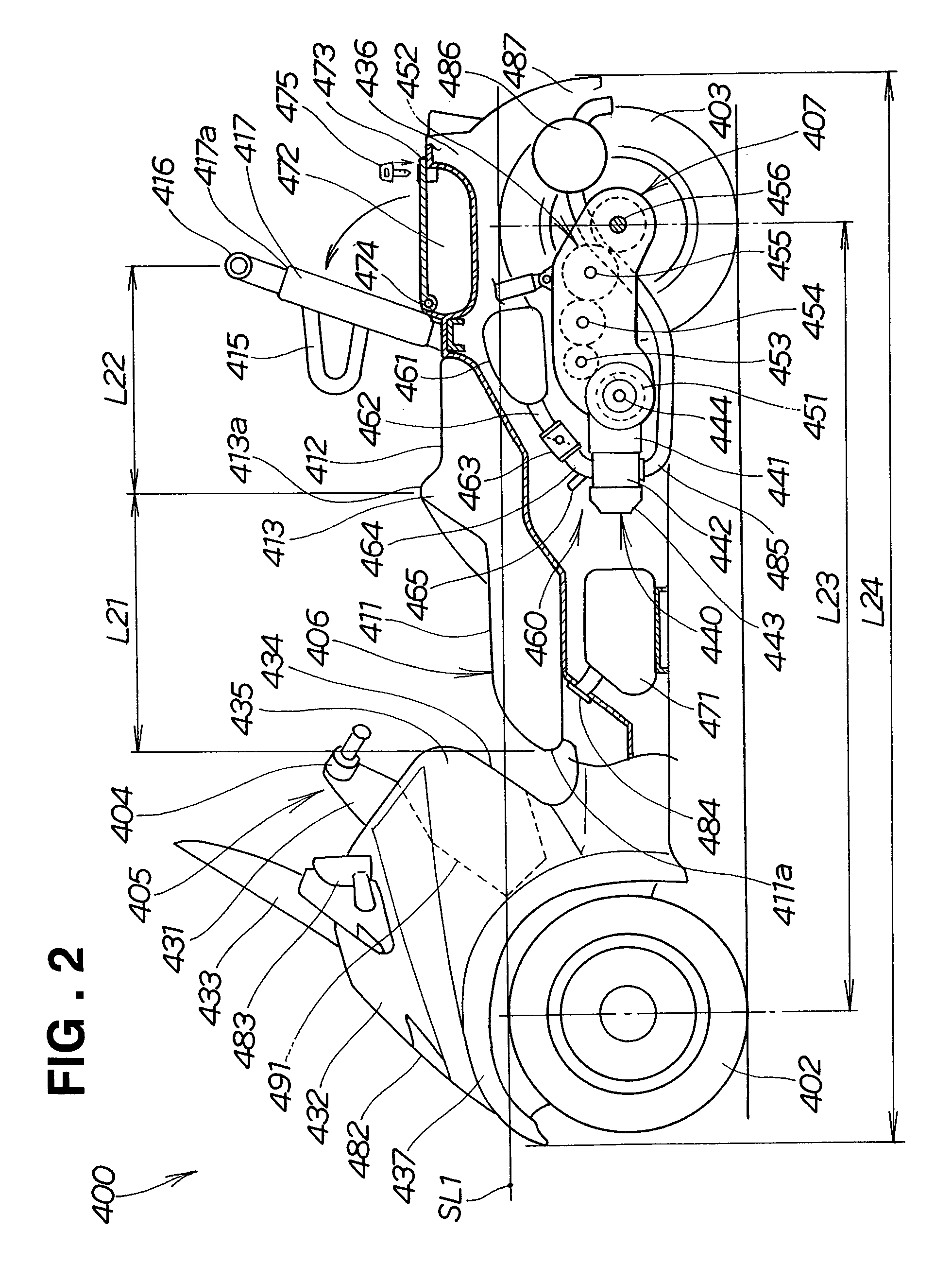
[0130]Referring to FIG. 1 and FIG. 2, there is shown a small-sized, four-wheeled vehicle 400 according to the present invention. The vehicle 400 includes a vehicle body 401. The vehicle body 401 includes right and left front wheels 402, 402 provided at right and left sides of a front part thereof, and right and left rear wheels 403, 403 provided at right and left sides of a rear part thereof. The vehicle body 401 has a seat 406 provided centrally thereof. The vehicle 401 includes a steering mechanism 405 provided at the front part thereof. The mechanism 405 has a bar handle 404. The vehicle 401 includes a power unit part 407 provided at the rear part thereof.

[0131]Each of the four wheels 402, 402, 403, 403 includes a tire having a diameter of 12 inches, for example.

[0132]The seat 406 extends longitudinally of the vehicle body 401. This type of seat is often called “tandem seat”. The seat 406 includes a driver's seat 411 provided at a front part thereof and a rear passenger seat 412 ...

fourth embodiment

[0216]Referring to FIG. 29 through FIG. 38, there is shown a roofed contractible four-wheeled vehicle 10 in accordance with the present invention.

[0217]As shown in FIG. 29 and FIG. 30, the roofed contractible vehicle 10 in the fourth embodiment is a two-seat scooter-type four-wheeled vehicle. The vehicle 10 has a front frame 20 provided at a front part thereof, and a rear frame 30 provided a rear part thereof. The front frame 20 includes two, or right and left front wheels 11, 11. The rear frame 30 has two, or right and left rear wheels 12, 12. The front frame 20 cooperates with the rear frame 30 to thereby bring the vehicle 10 from an extended state to a contracted state or vice versa, as will be described later. More specifically, the rear frame 30 is moved towards and away from the front frame 20 for contraction or extension of the vehicle 10. The roofed contractible vehicle 10 has its wheelbase variable to change the entire length thereof.

[0218]The front frame 20 includes its up...

fifth embodiment

[0250]As is clear from the above description, the roofed contractible vehicle 100 in the fifth embodiment has the driver's seat 35a movable in the front-and-rear direction and the roof 40 movable between convexly and more convexly curved states in response to the movement of the driver's seat 35a.

[0251]Reference is made to FIG. 49. When vehicles 81, 82 parked in tandem are spaced from each other by a distance slightly larger than the width of the roofed contractible vehicle 100 to thereby provide a free space S1, the roofed contractible vehicle 100 may be parked in the space S1 as follows.

[0252]First, the roofed contractible vehicle 100 travels in a direction perpendicular to a longitudinal direction of the vehicles 81, 82 for entry into the space S1. The vehicle 100 is then parked in orientation transverse with respect to the longitudinal direction of the vehicles 81, 82. Secondly, the driver and the passenger get off the vehicle 100 and then the roofed contractible vehicle 100 is...


PUM


Abstract

A four-wheeled vehicle includes a steering mechanism having a bar handle, right and left front wheels, and right and left rear wheels. The vehicle includes a front cover and a windshield disposed in front of the bar handle. The vehicle includes a driver's seat, and a rear passenger seat disposed behind the driver's seat and between the rear wheels. The rear passenger seat is directed forwardly. The vehicle includes a power unit part disposed below the rear passenger seat, and a body cover disposed rearwardly of the driver's seat.

Description

FIELD OF THE INVENTION[0001]The present invention relates to an improvement in a vehicle including a steering mechanism with a bar handle.BACKGROUND OF THE INVENTION[0002]Known vehicles include steering mechanisms having bar handles. Such vehicles are known from, for example, Japanese Patent Post-Exam Publication No. SHO 41-15969. The publication discloses a three-wheeled vehicle including two front wheels, one rear wheel, a steering mechanism having a bar handle, a driver's seat, and a passenger's seat disposed behind the driver's seat.[0003]The disclosed vehicle includes the single rear wheel positioned centrally of a rear part thereof. Since the rear part is mostly occupied by the rear wheel, such components as a power unit can not be disposed thereat. Therefore, the passenger's seat is inevitably positioned at a higher level above the rear wheel. With this arrangement, the vehicle undesirably has its center of gravity positioned higher. The vehicle should be improved to ensure t...

Claims


Application Information

Patent Timeline
IPC IPC(8): B60K5/00B60J5/00B60N2/01B60N2/24B60N2/30B60N2/36B60N2/90B60P3/42B60R21/13B62D21/14B62D21/18B62D31/00B62D47/00B62J1/12B62J25/00B62K5/01
CPCB60J5/0487B60N2/01B60N2/245B60N2/3013B60N2/36B60N2/449B60P3/423B62D21/14B62D21/183B62D31/003B62D47/003B62J1/12B62J7/02B62J17/00B62J25/00B62K5/01B60L11/1877B60G2200/132B60L2200/22B60G2300/40B60R21/13B60R2021/134Y10S180/908Y02T10/7005Y02T10/705B60G2300/13B60N2/986B60L50/66B62J25/04Y02T10/70B62D61/00B62K5/00
Inventor OZAWA, EIJIIIDA, OUMIHIGASHIHARA, SEIJISHIBATA, YUMIOSUGIOKA, KOICHIFUJIWARA, KIYOTAKAALLASIA, PAOLOFERRARIO, MARCOVERGANO, RAFFAELEWACHTLER, ANDREAS
Owner HONDA MOTOR CO LTD
Why Eureka
Try Eureka