Press-fit contact

a press-fit contact and contact technology, applied in the direction of coupling device details, coupling device connections, fixed connections, etc., can solve the problems of likely damage to the printed circuit board b>11/b>, and achieve the effect of avoiding damage to the board, easy twisting, and increasing the possibility of manufacturing methods

Inactive Publication Date: 2008-11-04
HONDA TSUSHIN IND
View PDF7 Cites 20 Cited by
  • Summary
  • Abstract
  • Description
  • Claims
  • Application Information

AI Technical Summary

Benefits of technology

[0010]The angle of the press-fit portion may be formed by twisting the bulge portion, and may also be formed by twisting the press-fit portion itself. In the case of twisting the bulge portion, the formation of a constricted portion with a thinned vertical center makes twisting easy, and is thus preferable. When multiple rows of through-holes are formed vertically and horizontally, it is most preferable that the rotation angle of the press-fit portion be approximately 45 degrees, because doing so gives the spaces between adjacent through-holes their largest values either from the vertical or the horizontal, and will not concentrate contact pressure due to press-fitting of the press-fit portions.
[0011]According to the press-fit contact of the present invention, the concentration of contact pressure between the through-holes of the printed circuit board by the press-fit portions of the press-fit contacts is eliminated, thereby enabling damage to the board to be avoided.
[0012]In addition, in order to rotate the expansion direction of the press-fit portion, two ways of twisting any of the expanded portion and the press-fit portion itself can be employed, which increases options for the manufacturing method.

Problems solved by technology

As described above, the printed circuit board 11 is likely to be damaged.

Method used


Image

  • Press-fit contact
  • Press-fit contact
  • Press-fit contact

Examples


first embodiment

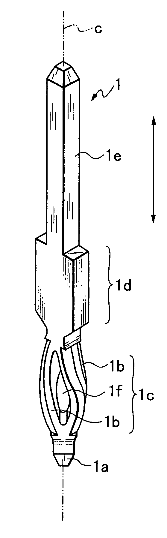
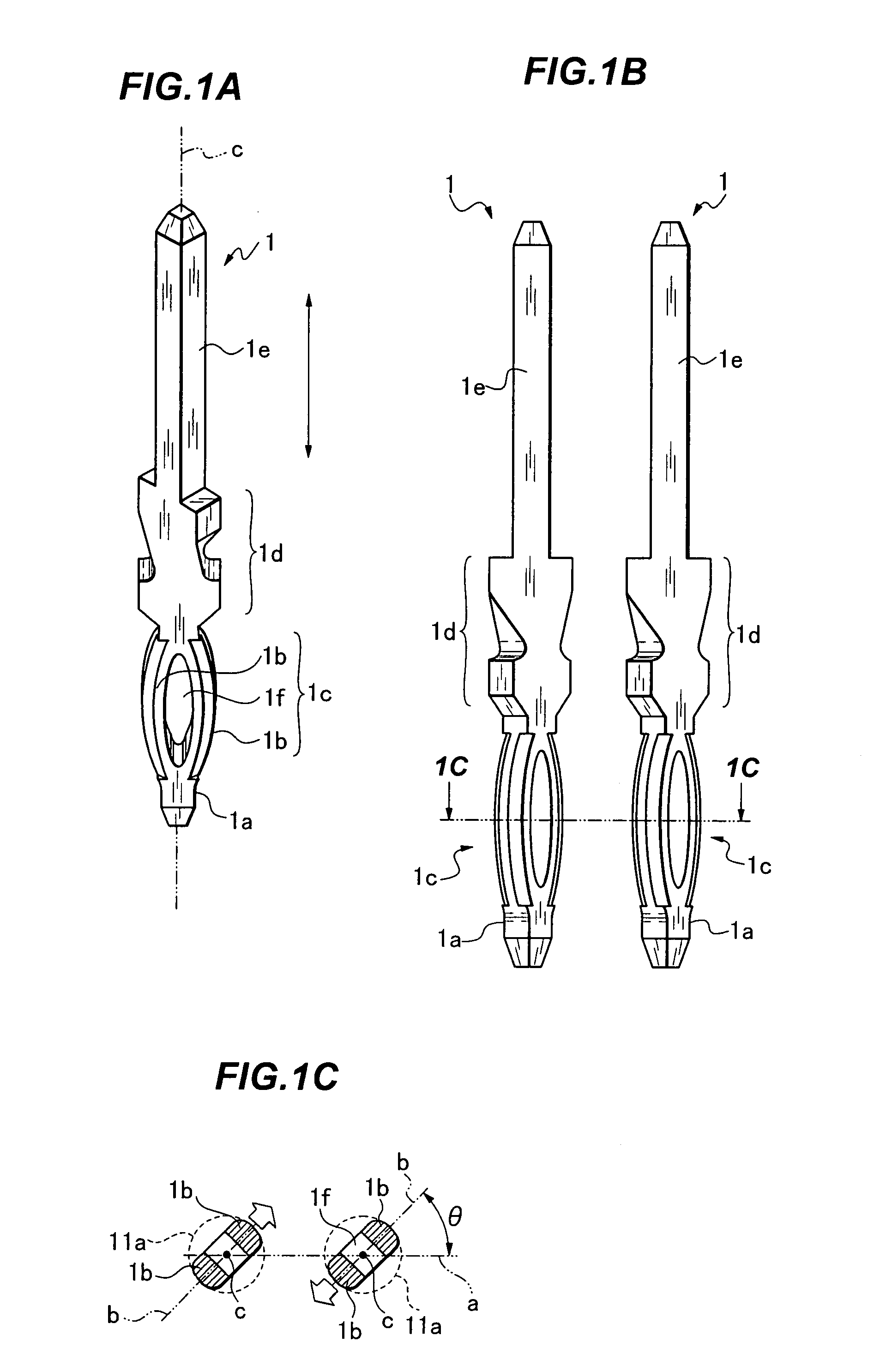
[0028]FIGS. 1A to 1C show a press-fit contact 1 according to the present invention, which includes a steeple like introduction portion 1a for introducing the contact 1 into the through-hole 11a (see FIGS. 7C and 8) of the printed circuit board, a press-fit portion 1c adapted to have expanded portions 1b, 1b projecting along both sides in the shape of an arc while forming an elliptical slit 1f, a bulge portion 1d extended from the press-fit portion 1c and fixed in a fixing hole of an insulating housing, and a contact portion 1e extended from the bulge portion 1d. The press-fit portion 1c is press-fitted into the through-hole 11a of the printed circuit board.

[0029]The expanded portions 1b, 1b of the press-fit portion 1c projecting in the shape of an arc are twisted around their shaft center “c” in a circumferential direction as shown in FIG. 1C. As a result, when a plurality of press-fit contacts 1 is arranged in parallel in alignment with a line “a”, the expanded portions 1b, 1b of a...

second embodiment

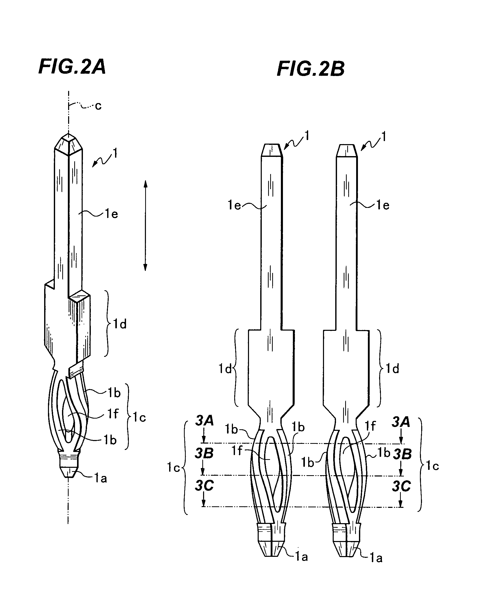
[0030]FIGS. 2A and 2B show a press-fit contact 1 where the press-fit portion 1c itself is twisted. As shown in FIG. 2B, when three horizontal cross-sections 3A, 3B, and 3C are viewed vertically from the top, the press-fit contact 1 is not yet twisted in the cross-section 3A as shown in FIG. 3A, is rotated by an angle θ1 with respect to a line “a” in the cross-section 3B as shown in 3B, and is rotated by an angle θ2 (θ2>θ1) in the cross-section 3C as shown in 3C. More specifically, the expanded portions 1b, 1b of the press-fit portion 1c are twisted around the shaft center “c” in a circumferential direction to form a spiral shape.

[0031]When the press-fit contacts 1 according to the present invention formed as described above are press-fitted into the through-holes 11a of the printed circuit board 11, as shown in FIG. 4, the arrangement of the contacts in alignment with a line a1 brings the expansion directions “b” of the expanded portions 1b, 1b parallel to each other at an angle θ ...


PUM


Abstract

To prevent damage to a printed circuit board due to concentration of contact pressure during press-fitting of press-fit contacts into through-holes of the board with narrow pitches, a press-fit contact includes a bulge portion formed wide substantially at a center in a long direction thereof, a press-fit portion extending from one end of the bulge portion and projecting in an arc in a width direction of the press-fit contact, a contact portion extending from the other end of the bulge portion, and an introduction portion extending from a distal end of the press-fit portion. A center portion of the press-fit portion in the long direction thereof, when adjacent press-fit contacts are provided in alignment with a line, has a direction of expansion that is not parallel to the line but is angled so as to be rotated about an axis of the center portion at a predetermined angle.

Description

BACKGROUND OF THE INVENTION[0001]1. Field of the Invention[0002]The present invention relates to a press-fit contact in which press-fitting into a through-hole of a printed circuit board effects an electrical connection.[0003]2. Related Art[0004]Conventionally, for a connector that is to be mounted on a printed circuit board, contacts for electrical connection to a circuit in the printed circuit board are provided and fixed in place by soldering. However, in recent years, from the viewpoint of solder-free connection or operating efficiency, connectors using press-fit contacts have come to be used.[0005]Such a press-fit contact 10, as shown in FIGS. 7A, 7B, and 7C, is punched out of a sheet of material, and includes an introduction portion 10a for introducing the contact 10 into a through-hole 11a of a printed circuit board 11, a press-fit portion 10b, an expanded portion 10c, and a contact portion 10d. The press-fit portion 10b is formed between the expanded portion 10c and the intr...

Claims


Application Information

Patent Timeline
Patent Type & Authority Patents(United States)
IPC IPC(8): H01R13/60H01R12/58
CPCH01R12/585H01R43/205
Inventor NUNOKAWA, CHIHARUIIJIMA, SATOSHI
Owner HONDA TSUSHIN IND
Why Eureka
Try Eureka