Press-fit contact
- Summary
- Abstract
- Description
- Claims
- Application Information
AI Technical Summary
Benefits of technology
Problems solved by technology
Method used
Image
Examples
first embodiment
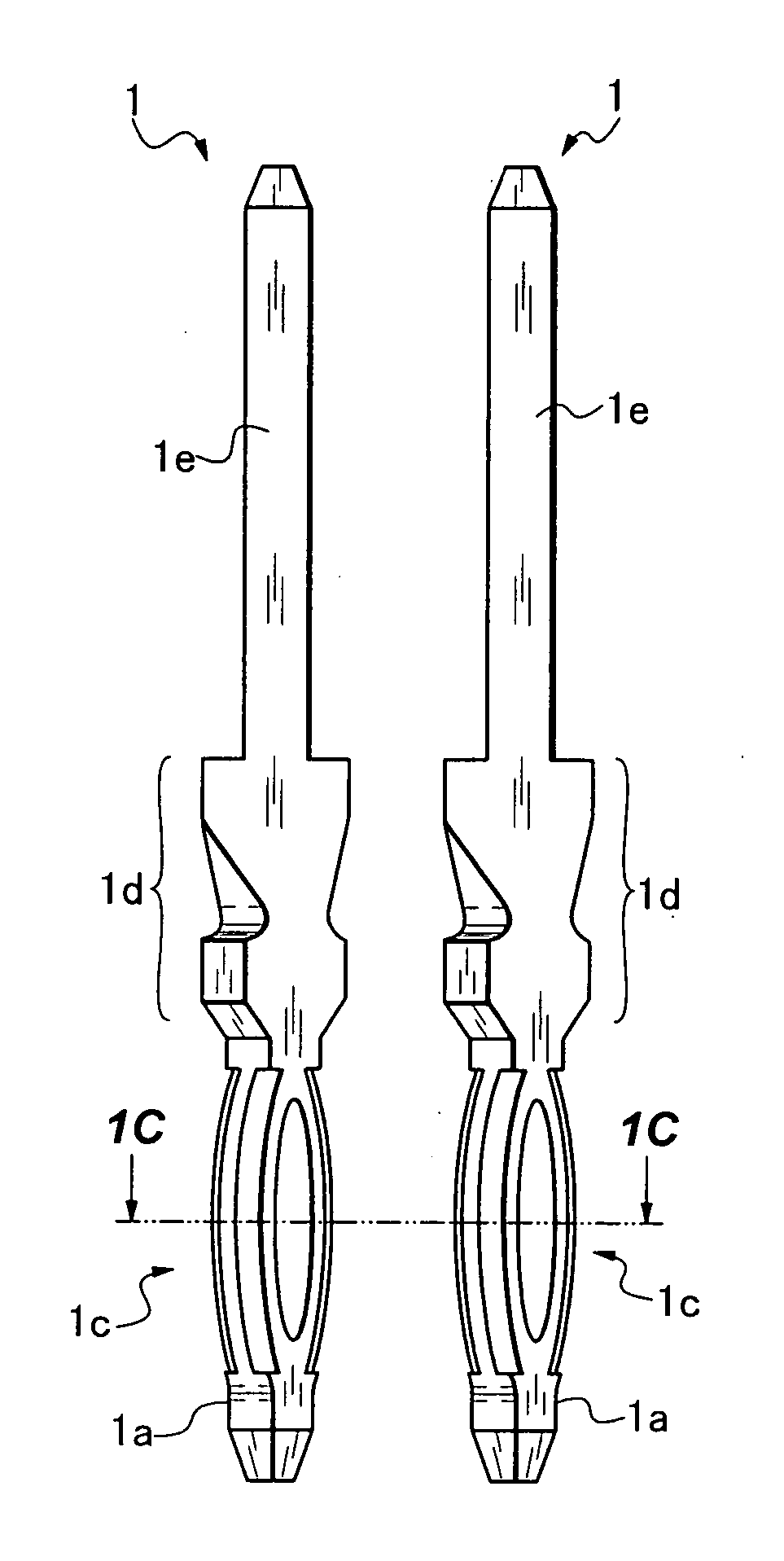
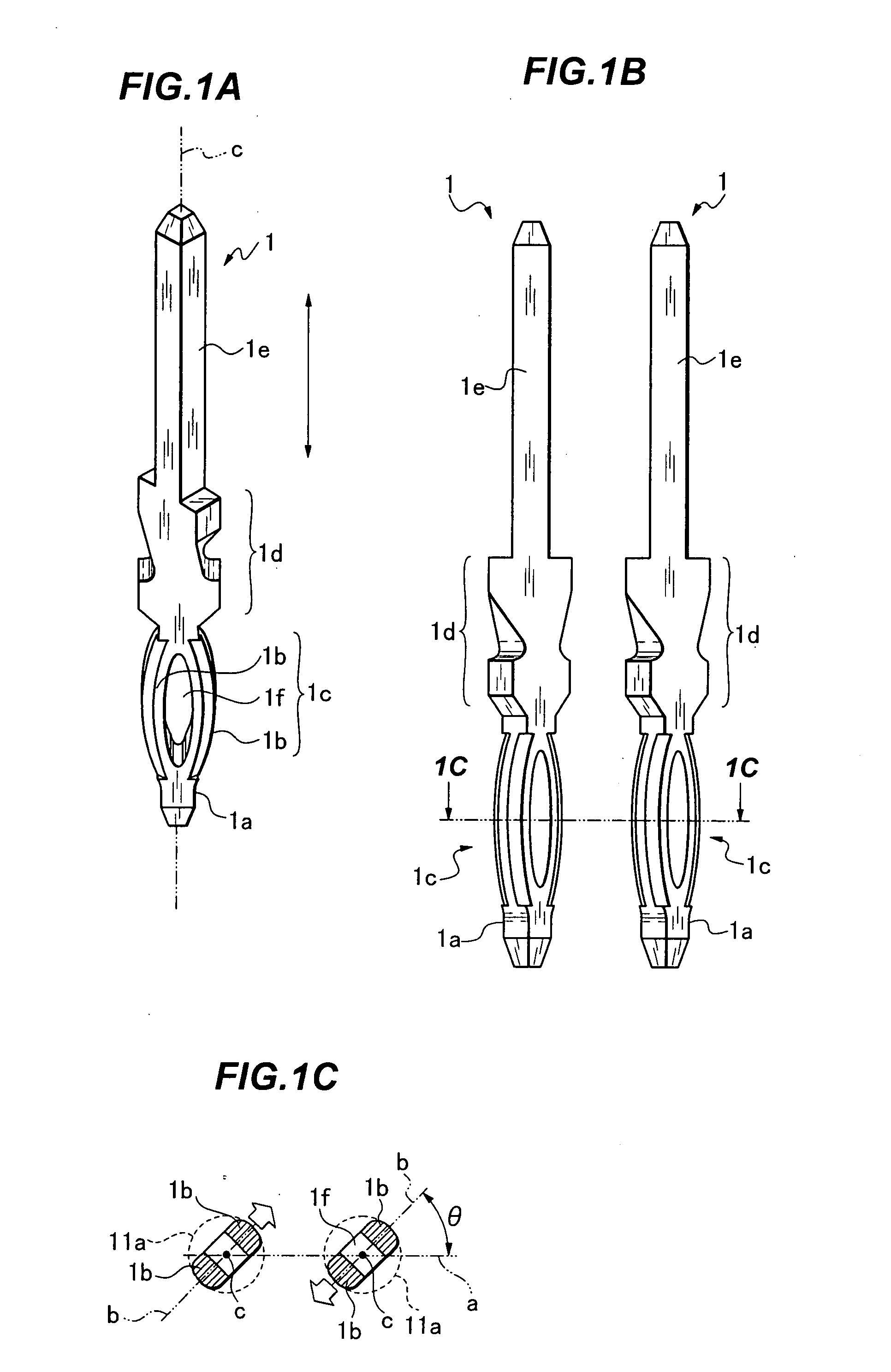
[0028]FIGS. 1A to 1C show a press-fit contact 1 according to the present invention, which includes a steeple like introduction portion 1a for introducing the contact 1 into the through-hole 11a (see FIGS. 7 and 8) of the printed circuit board, a press-fit portion 1c adapted to have expanded portions 1b, 1b projecting along both sides in the shape of an arc while forming an elliptical slit 1f, a bulge portion 1d extended from the press-fit portion 1c and fixed in a fixing hole of an insulating housing, and a contact portion 1e extended from the bulge portion 1d. The press-fit portion 1c is press-fitted into the through-hole 11a of the printed circuit board.
[0029]The expanded portions 1b, 1b of the press-fit portion 1c projecting in the shape of an arc are twisted around their shaft center “c” in a circumferential direction as shown in FIG. 1C. As a result, when a plurality of press-fit contacts 1 is arranged in parallel in alignment with a line “a”, the expanded portions 1b, 1b of ad...
second embodiment
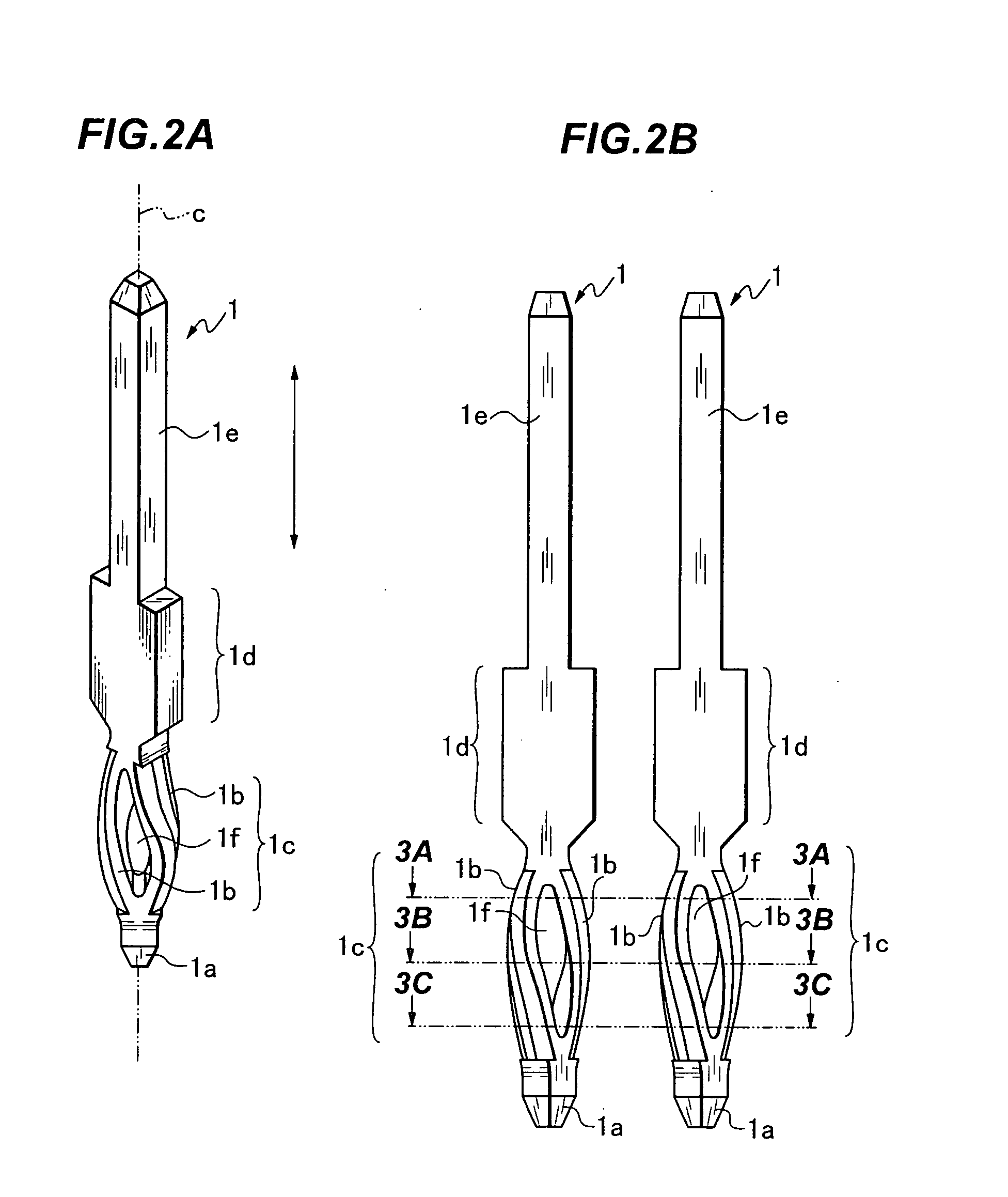
[0030]FIGS. 2A and 2B show a press-fit contact 1 where the press-fit portion 1c itself is twisted. As shown in FIG. 2B, when three horizontal cross-sections 3A, 3B, and 3C are viewed vertically from the top, the press-fit contact 1 is not yet twisted in the cross-section 3A as shown in FIG. 3A, is rotated by an angle θ1 with respect to a line “a” in the cross-section 3B as shown in 3B, and is rotated by an angle θ2 (θ2>θ1) in the cross-section 3C as shown in 3C. More specifically, the expanded portions 1b, 1b of the press-fit portion 1c are twisted around the shaft center “c” in a circumferential direction to form a spiral shape.
[0031]When the press-fit contacts 1 according to the present invention formed as described above are press-fitted into the through-holes 11a of the printed circuit board 11, as shown in FIG. 4, the arrangement of the contacts in alignment with a line a1 brings the expansion directions “b” of the expanded portions 1b, 1b parallel to each other at an angle θ ...
PUM
 Abstract
Description
Claims
Application Information
 - R&D
- Intellectual Property
- Life Sciences
- Materials
- Tech Scout
- Unparalleled Data Quality
- Higher Quality Content
- 60% Fewer Hallucinations
Browse by: Latest US Patents, China's latest patents, Technical Efficacy Thesaurus, Application Domain, Technology Topic, Popular Technical Reports.
© 2025 PatSnap. All rights reserved.Legal|Privacy policy|Modern Slavery Act Transparency Statement|Sitemap|About US| Contact US: help@patsnap.com


