Super bright LED utility and emergency light

a super bright, led technology, applied in the direction of power connection, built-in power connection, ways, etc., can solve the problems of reducing the reducing the service life of the lighting bulb, so as to achieve the effect of reducing significant electrical work

Inactive Publication Date: 2006-05-30
SUNCOR STAINLESS
View PDF24 Cites 18 Cited by
  • Summary
  • Abstract
  • Description
  • Claims
  • Application Information

AI Technical Summary

Benefits of technology

[0013]The present invention uses of only one continuous electric supply line, and LED connections are made to that supply line by pushing the LED into its specially shaped recess, and thus forcing the prongs to puncture the plastic coating of the electric supply line and make a direct connection. This eliminates significant electrical work, usually required with standard lights having two leads protruding from them and therefore requiring individual electric connections to those. The use of uniform orientation of the supply line throughout the supply housing ensures that the same supply line from the power source can be used throughout the installation. The supply line can be easily twisted through holes in posts, plates, stanchions or similar supports, but regardless of such contortions will still be aligned properly in the supply housing with respect to the lights source prong / leads. This is especially important with LEDs, which function only with proper polarity.
[0014]The use of one electrical supply line in the supply housing provides the maximum flexibility to mount LED lights anywhere along the housing, and also allows differently shaped mounting bars to be used to conform with the design of the structure (e.g., railing system) within which it is employed. This allows use in both new and existing retrofit railing systems, regardless of the construction of those railing systems, and further permits use of the present invention for many other applications not mentioned herein, provided the supply housing bar and a mounting bar can be mounted to a surface of a structure.

Problems solved by technology

These types of lighting systems are relatively inefficient.
A substantial amount of energy is lost generating heat as a byproduct.
Another disadvantage of these types of systems is the relatively short life span of the lighting bulbs.
Consequently, these lighting systems result in high operational and maintenance costs.
There remain problems relating to the costs and adaptability of light emitting diodes (LED's) to electricity supply lines in structures such as, for example, new and existing railing systems.

Method used


Image

  • Super bright LED utility and emergency light
  • Super bright LED utility and emergency light
  • Super bright LED utility and emergency light

Examples


Embodiment Construction

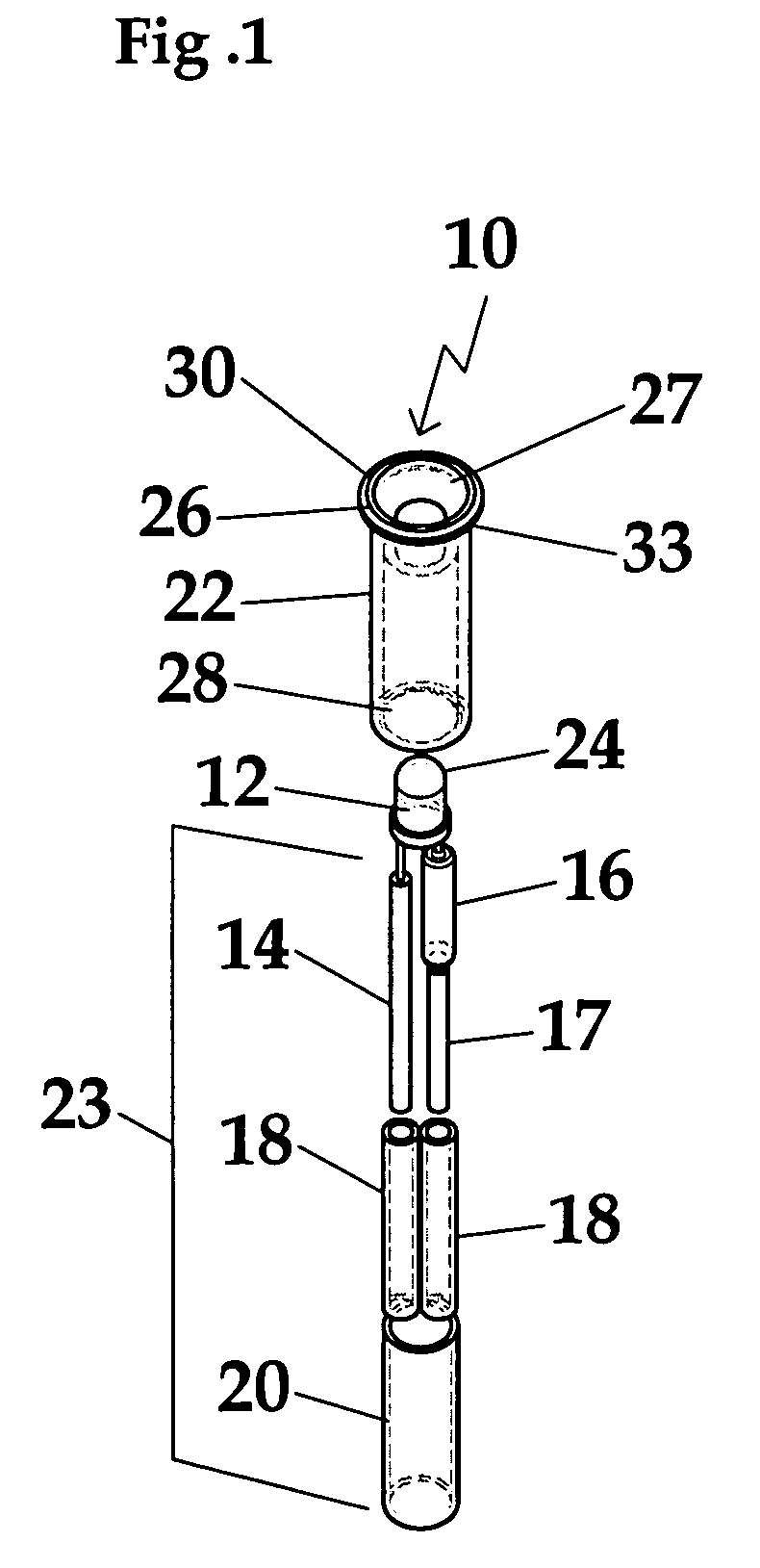
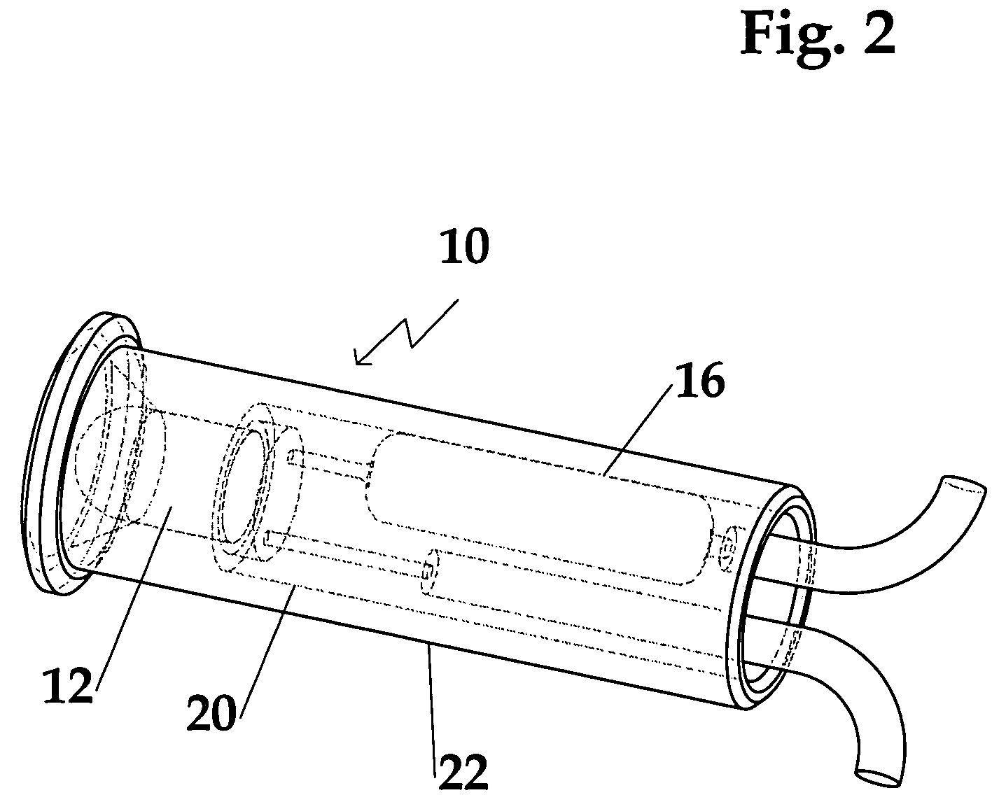
[0035]With reference to FIGS. 1 and 2, a non-limiting example of miniature light assemblies 10 used in the inventive lighting bar system of the present invention includes a bright white LED 12, an electric insulated wire having a negative lead 14 connected to the LED 12, a resistor 16 connected to the LED 12, and an electric insulated wire having a positive lead 17 connected to the resistor 16. The term “wire” as used herein refers to a conductive material having sufficient strength and rigidity to puncture the plastic coatings found on conventional electrical supply lines. The portion of the wires protruding from the housing are referred to below as ‘prongs’, and they may include tapered or beveled ends to facilitate the puncturing of the electrical supply line coatings. The resulting LED connections may be covered by a small, inner piece of shrink-tube 18 after which the complete component assembly 23 is covered by an outer shrink-tube 20, which all together prevent any electrical...


PUM


Abstract

Lighting system mountable on a surface and including one or more miniature light sources and a multi-part housing including recesses for accepting the light sources and an electrical supply line. The light sources can include light emitting diodes. Separate parts of the housing are mated in a manner to fix the position of the electrical supply line between them, and may be formed with a recess that receives an asymmetrically shaped electrical supply line in only one possible orientation. Similarly, the recesses receiving the light sources may be shaped such that electrical connections with proper polarity are assured. Either or both parts of the housing may be fastened to the surface with adhesives and/or optional holes for receiving pins, nails, screws, bolts or the like. The lighting system is particularly suitable for emergency, railing, landscape and vehicle illumination applications, and may be powered by batteries and renewable energy sources.

Description

CROSS REFERENCE TO RELATED PATENT APPLICATIONS[0001]This application is a continuation-in-part of U.S. patent application Ser. No. 09 / 968,560 entitled “Super Bright LED Utility And Emergency Light”, filed Oct. 1, 2001, now U.S. Pat. No. 6,676,278, which claims priority of U.S. Provisional Application Ser. No. 60 / 237,012 entitled “Super Bright LED Utility And Emergency Light”, filed Sep. 29, 2000, all of the above being incorporated herein by reference.FIELD OF THE INVENTION[0002]The present invention relates generally to electrical lighting and, more particularly, to easily installed recessed lighting for use with railings and similar structures.BACKGROUND OF THE INVENTION[0003]Miniature illumination lighting devices have historically used incandescent or halogen bulbs. These types of lighting systems are relatively inefficient. A substantial amount of energy is lost generating heat as a byproduct. Another disadvantage of these types of systems is the relatively short life span of t...

Claims


Application Information

Patent Timeline
Patent Type & Authority Patents(United States)
IPC IPC(8): H01R33/00E04F11/18F21K99/00F21V21/28F21V23/04F21V29/00F21V31/00F21Y101/02
CPCF21V23/0442F21V31/005E04F2011/1048E04F2011/1872F21S9/022F21S9/03F21Y2101/02F21W2111/027F21W2111/08F21V21/28F21Y2115/10
Inventor STRIEBEL, ROMAN F.
Owner SUNCOR STAINLESS
Why Eureka
Try Eureka