Combination chair and leg extension apparatus for obesity prophylaxis

a technology of leg extension and obesity prophylaxis, which is applied in the field of chairs, can solve the problems of expensive equipment, such as treadmills and stationary bicycles, and the most difficult thing to exercis

Inactive Publication Date: 2008-11-04
GIBSON JOHN
View PDF126 Cites 18 Cited by
  • Summary
  • Abstract
  • Description
  • Claims
  • Application Information

AI Technical Summary

Benefits of technology

[0012]It is believed that the combination chair and leg-extension apparatus will provide a convenient and accessible means of developing and strengthening the leg muscles, and thus act as a catalyst that will incite human beings to be physically active.
[0016]For safe and compact storage, it is preferred that the apparatus in stowed position does not extend in any direction beyond the outer dimensions of the chair. Alternatively, the apparatus may be designed to fit within the dimensions established by an area bounded by the legs of the chair.
[0019]The apparatus permits a user seated in the chair to engage the stirrups with the user's feet and, using the force of the user's leg strength to overcome the resistence provided by the resistor, the user can kick the flexor leg forward in an arc, thereby drawing forward the tube to fully extend the flexor leg and tube forwardly away from the chair.
[0024]The apparatus permits a user seated in the chair to pivot forward the apparatus from the stowed position and to engage the stirrups with the user's feet. Using the force of the user's leg strength to overcome the resistence provided by the resistor, the user can kick the flexor leg forward in an arc, thereby drawing forward the tube to fully extend the flexor leg and tube forwardly away from the chair.
[0026]The recline may provide additional clearance to keep the apparatus off the floor as it sweeps in its arc. The height adjustability of the pedestal base may also permit additional clearance between the arc described by the apparatus and the floor. Preferably, the leg extension apparatus does not touch the floor at any point. Preferably, the apparatus does not touch the pedestal base at any point.

Problems solved by technology

In most households, expensive equipment, like treadmills and stationary bicycles, just sit there; either broke down or used for hanging laundry.
This is because one of the most difficult things to do is to exercise for the sake of exercising.

Method used


Image

  • Combination chair and leg extension apparatus for obesity prophylaxis
  • Combination chair and leg extension apparatus for obesity prophylaxis
  • Combination chair and leg extension apparatus for obesity prophylaxis

Examples


first embodiment

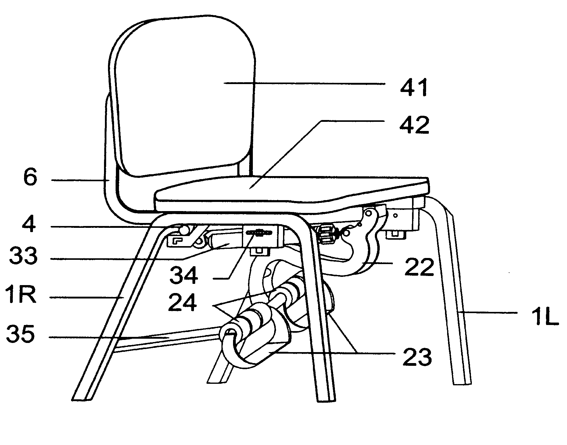
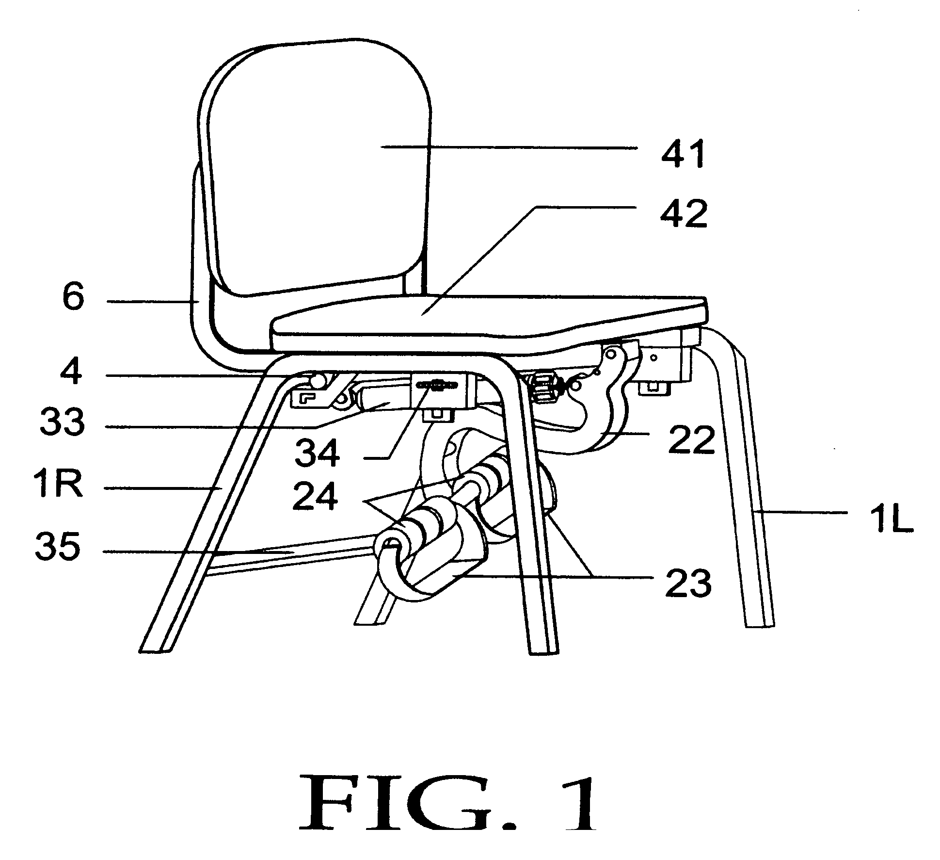
[0066]Turning now to a detailed description of the preferred embodiments, FIG. 1 illustrates a straight back chair with reclining capabilities with a leg extension apparatus in place under the chair seat. The chair legs 1 start with the front leg at the floor extending upwards to a bend continuing across the top forming the base to a downward bend forming the rear leg to come in contact with the floor. The right legs are preferably rigidly connected to corresponding left chair legs by a web horseshoe stabilizing plate so placed to prevent leg spread, the stabilizing plate so illustrated in FIG. 3. A rear lower leg stabilizing spreader bar 35 rigidly secures the right leg to the corresponding left leg 1. A rear top roll bar 4 extends from under the top rear right leg 1, bends to the underside of the corresponding top rear left leg 1, rigidly securing the rear edge of the horseshoe web. The web is so contoured as to come in contact with the underside of the upper right leg 1, and left...

second embodiment

[0089]FIG. 24 illustrates the second embodiment, a combination chair, desk and leg extension apparatus. The embodiment allows the chair to be combined for multi-tasking in the course of seated activity. One possible use of the second embodiment is as a student's school desk. FIG. 24 shows mounting bracket 69, A & B with sliding capabilities and height-adjustable desk platform 38.

[0090]FIG. 25 is a further illustration of the second embodiment, with the desk top 38, which is preferably rigidly secured and mounted on frame 40, having four telescoping legs 36, at least two of which are pneumatically adjustable 71. As shown, release lever 72 allows the pneumatic height adjustment. In a generally U-shaped frame, the legs 36, extend from the desk top frame 40, take a 90% turn to a vertical, continuing from the desk frame to the contour of the floor part of the frame, where they join the pneumatic shock absorber telescoping legs 71, then continue on to the rear contour up to the stabilizer...

third embodiment

[0093]FIG. 29 illustrates a schematic view of a third embodiment. In combination with an office chair, a variation of the leg extension apparatus is illustrated in its stowed position, connected to the chair by the use of the arm frame 81. Right and left arms are preferably rigidly connected together by two cross members one under the forward seat part and one to the back supporting of the chair back. The arms are interrupted just below their downward bending contour by an bearing hinge 72, which allows the leg extension apparatus to pivot in an oscillating motion when the flexor leg parts 73, 75, 76, 77, and 80, are in operational mode.

[0094]The chair preferably has a pneumatic height adjustment 79 to vary the distance between the seat portion and the base 78 (shown here with casters).

[0095]FIG. 30 is a view of the underseat tilt holding block mechanism 85, and finger operated handle 82, which, when activated, will maintain the office chair in a 10° tilted angle. When the chair sea...


PUM


Abstract

A combination chair and leg extension apparatus is provided. The apparatus uses a pneumatic source of resistence to provide a stowable flexor for the leg muscles which remains connected to the chair. Variations of the combination also provide for a combination desk, chair and leg extension apparatus, and a combination office chair and leg extension apparatus. The invention is to assist in prevention of obesity, particularly in children.

Description

CROSS-REFERENCE TO RELATED APPLICATIONS[0001]This application claims benefit of U.S. provisional patent application Ser. No. 60 / 671,525, filed Apr. 15, 2005, which is herein incorporated by reference.FIELD OF THE INVENTION[0002]The invention relates to chairs and, more particularly, to chairs permitting seated leg flexion for muscle development.BACKGROUND OF THE INVENTION[0003]There is a growing awareness of obesity and the human health problems it causes. In order to address this problem, there seems to be general agreement that a proper diet and a variety of physical activities are needed.[0004]In order to attack this problem at its origin, there is an increasing recognition that the physical activity habits of children are key. Growing children need to develop and utilize their muscles.[0005]We do not exist in a culture that lends itself to physical activity. The modern lifestyle is founded on and depends upon transportation, which has eliminated most physical activities and duti...

Claims


Application Information

Patent Timeline
Patent Type & Authority Patents(United States)
IPC IPC(8): A63B26/00
CPCA47C7/503A47C9/002A61G15/007A63B23/0494A63B21/0087A63B2021/1609A63B21/1609
Inventor GIBSON, JOHN
Owner GIBSON JOHN
Why Eureka
Try Eureka