Apparatus for controlling the delivery of medical fluids

a technology for medical fluids and apparatuses, applied in the direction of intravenous devices, other medical devices, therapy, etc., can solve the problems of increasing the difficulty of patient therapy and additional expenses

Active Publication Date: 2008-11-04
DRAGERWERK AG
View PDF8 Cites 18 Cited by
  • Summary
  • Abstract
  • Description
  • Claims
  • Application Information

AI Technical Summary

Benefits of technology

[0011]The advantage of the invention is essentially that for monitoring the medical fluid delivery, one additional patient model is used, with which, from past and current values of the dosage rate, a future medical fluid concentration that will become established in the patient's body is extrapolated.
[0012]In a safety device, a comparison of the extrapolated medical fluid concentration with a limit value for the maximum medical fluid concentration is performed, and if the limit value is exceeded, the dosage unit is switched off. From the extrapolation of the medical fluid concentration using a patient model, predictive monitoring values are available, in contrast to a measurement that refers only to the current instant of measurement. Thus with the patient model, medical fluid concentrations that will become established within the next minute or the next half hour can thus be calculated in advance. Critical situations can thus be recognized early, without impairing patient therapy.
[0013]Advantageous features of the invention will become apparent from the dependent claims.
[0014]Expediently, EEG measurement signals of the patient are for instance assessed as the body effect, and from this, BIS® levels are ascertained, which are a measure of the depth of hypnosis. (BIS®: Bispectral Index)
[0015]As an alternative to EEG measurement signals, muscle responses stimulated by a stimulating current or a sequence of stimuli may be assessed as the body effect. Muscle responses can be detected quantitatively for instance via a force measurement or a measurement of the electrical activity, or by means of acceleration measurement.
[0016]For extrapolating the medical fluid concentration using the additional patient model, the period of time extends expediently over a range of from 3 minutes to 30 minutes.

Problems solved by technology

However, in nearly all anesthetics, the total of these two quantities does not represent the administered dose; instead, there is always a missing quantity.
However, a further sensor entails additional expense and, because it means a further cable connection, makes provisions for patient therapy more difficult.

Method used


Image

  • Apparatus for controlling the delivery of medical fluids
  • Apparatus for controlling the delivery of medical fluids

Examples


Embodiment Construction

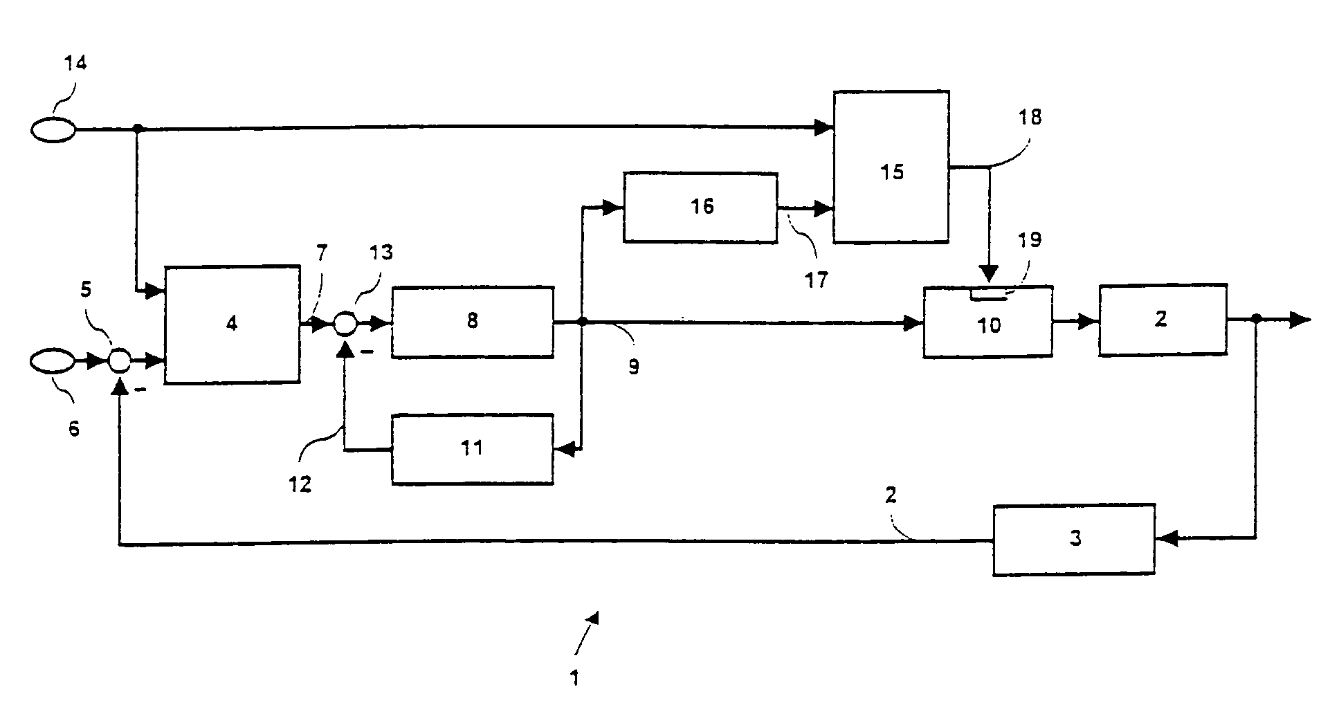
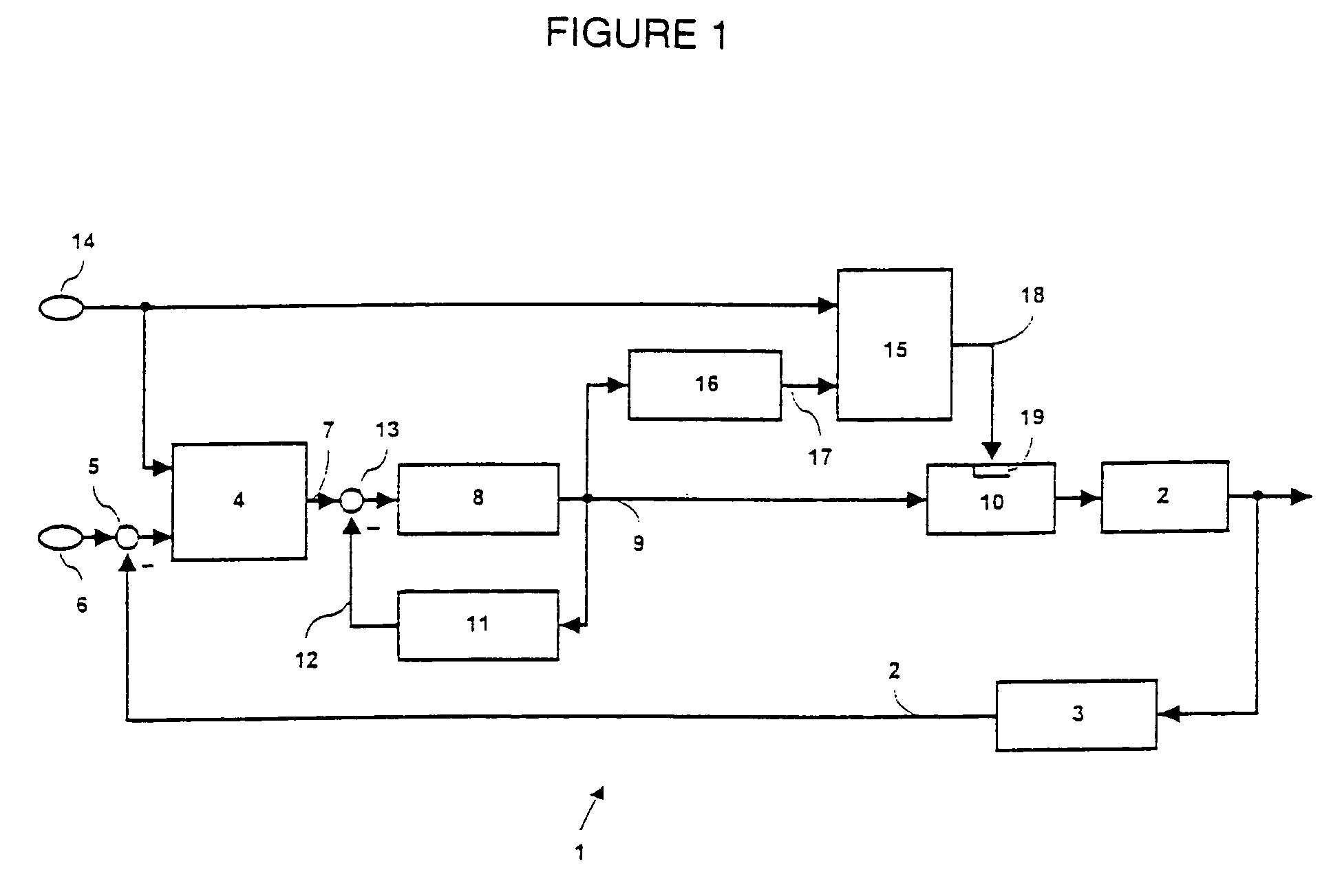
[0020]The sole FIGURE of the drawing illustrates a regulating apparatus 1 for setting a predetermined depth of hypnosis in a patient 2. By means of a measuring instrument 3 at the patient 2, EEG measurement signals are detected, and from them a BIS® level is ascertained as an actual value for the depth of hypnosis. A target variable 6 for the BIS® level is set by a desired value setter. A body effect calculation unit 4, which receives an input variable from a comparator 5 in the form of the difference between the target BIS® value 6 and the actual BIS® value forms a control input 7 from this for the medical fluid concentration to be established, for instance the plasma concentration, in the body of the patient 2. The body effect calculation unit 4 is followed by a medical fluid regulating device 8, which furnishes a dosage rate 9 for a medical fluid dosage unit 10. The dosage rate 9 is supplied as an input variable to a patient model 11, in which the current medical fluid concentrat...


PUM


Abstract

An apparatus for medical fluid delivery is to be improved for the sake of simple monitoring of the quantity of medical fluid delivered. For attaining this object, a safety device (15) with a patient model (16) is provided, which from past values and current values of the dosage rate of the medical fluid extrapolates a future medical fluid concentration (17) and switches off the dosage unit (10) for the medical fluid if the extrapolated medical fluid concentration (17) exceeds a predetermined limit value (14).

Description

CROSS-REFERENCES TO RELATED APPLICATIONS[0001]This application is based on and incorporates herein by reference German Patent Application No. DE 102004032814.5 filed on Jul. 7, 2004.BACKGROUND OF THE INVENTION[0002]The invention relates to an apparatus for controlling the delivery of medical fluids to a patient.[0003]In determining the proper dosage of medical fluids, closed-loop control circuits are used to set a defined depth of hypnosis, analgesia, or degree of relaxation. As dosage devices, syringe pumps with which the medical fluids can be delivered to the patient are known. The resultant medical fluid concentration, such as the enrichment of medical fluid in the blood plasma, can be determined only by drawing blood and then examining it. In conjunction with certain medications, so-called patient models have therefore been developed, with which the medical fluid enrichment in the blood plasma can be simulated mathematically. The patient models that have been known until now app...

Claims


Application Information

Patent Timeline
Patent Type & Authority Patents(United States)
IPC IPC(8): A61M31/00
CPCA61M5/1723A61M2205/52
Inventor BUNKE, CLAUSDITTMAN, RALFKAUFMANN, BERNDKOHNE, JENSMANIGEL, JURGENPANITZ, GERALD
Owner DRAGERWERK AG
Why Eureka
Try Eureka