
SAR hotspot reduction by temporal averaging in parallel transmission MRI

a technology of parallel transmission and sar, applied in the field of magnetic resonance arts, can solve the problems of mr imaging applications, sar becomes a limiting factor for many, and the potential heating of tissue, so as to improve image contrast, shorten acquisition time, and increase duty cycle and flip angle

Active Publication Date: 2012-01-19
KONINKLIJKE PHILIPS ELECTRONICS NV
View PDF4 Cites 11 Cited by
  • Summary
  • Abstract
  • Description
  • Claims
  • Application Information

AI Technical Summary

Benefits of technology

[0009]One advantage is that increased duty cycle and flip angle can be achieved to shorten acquisition times and improve image contrast.
[0011]Another advantage is that higher field strengths can be utilized. Another advantage is that patient safety is improved.

Problems solved by technology

Radiofrequency (RF) pulses applied during MR imaging causes potential heating of tissue due to the RF power or energy absorbed.
The SAR becomes a limiting factor for many MR imaging applications because it is dependent on field strength, RF power, flip angle, transmit coil type, and body size.
It is possible to limit the magnitude of hot spots by limiting the amplitude and increasing the duration of the RF pulses; however, in certain imaging sequences the contrast is dependent on the flip angle of the RF excitation pulse and increased duration may yield motion artifacts.

Method used


Image

  • SAR hotspot reduction by temporal averaging in parallel transmission MRI
  • SAR hotspot reduction by temporal averaging in parallel transmission MRI
  • SAR hotspot reduction by temporal averaging in parallel transmission MRI

Examples


Embodiment Construction

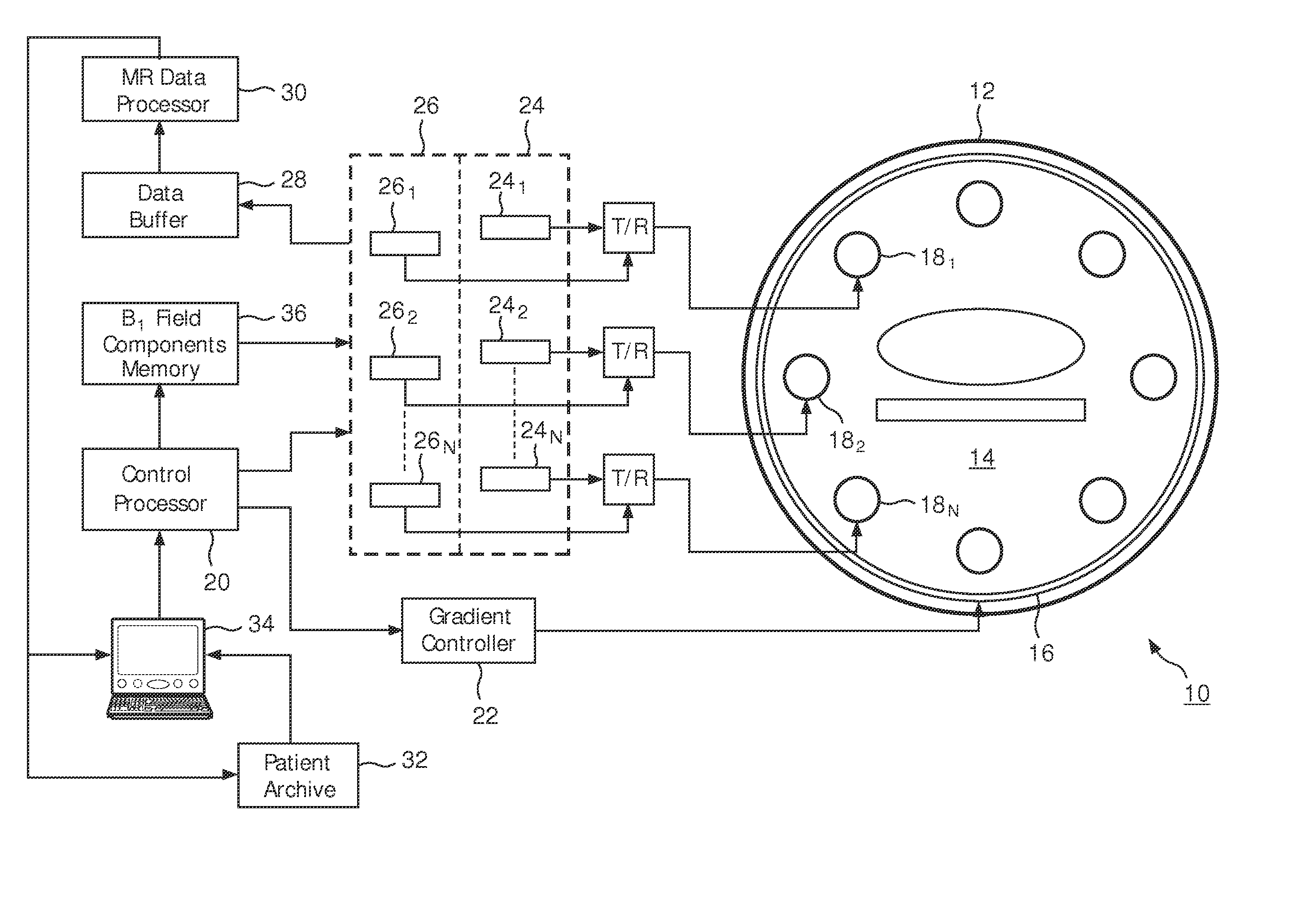
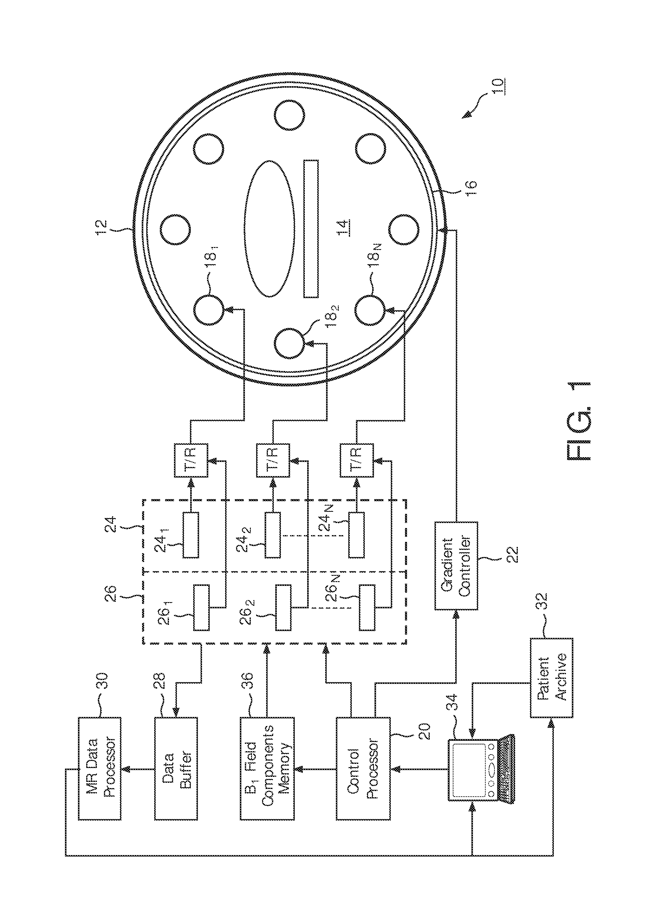
[0018]With reference to FIG. 1, a magnetic resonance imaging system 10 includes a main magnet 12 which generates a temporally uniform B0 field through an examination region 14. The main magnet can be an annular or bore-type magnet, a C-shaped open magnet, other designs of open magnets, or the like. Gradient magnetic field coils 16 disposed adjacent the main magnet serve to generate magnetic field gradients along selected axes relative to the B0 magnetic field. A radio frequency coil or coil array 18, including a plurality of discrete RF elements 181, 182 . . . 18N is disposed adjacent the examination region. In a multi-coil array, each discrete RF element would be an independently operable RF coil.

[0019]A scan control processor 20 controls a gradient controller 22 which causes the gradient coils to apply selected magnetic field gradient pulses across the imaging region, as may be appropriate to a selected magnetic resonance imaging or spectroscopy sequence. The scan controller 20 al...


PUM


Abstract

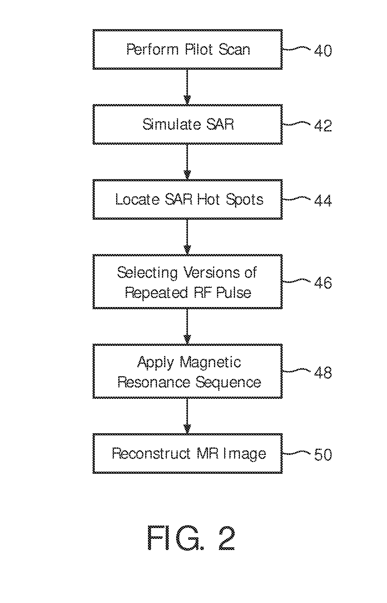
A magnetic resonance sequence includes a repetitively applied radiofrequency B1 pulse capable of causing a specific absorption rate (SAR) hot spot. The composition of the repetitive B1 pulse is varied to generate versions of the repetitive B1 pulse such that the SAR hot spot changes locations with subsequent applications of the repetitive B1 pulse. To generate versions of the B1 pulse, a pilot scan is performed to generate a patient model. A simulation of the SAR response to each of the versions of the repetitive B1 pulse is performed to determine the location of SAR hot spot(s). A plurality of versions of the repetitive B1 pulse is selected to be used in the magnetic resonance sequence.

Description

FIELD OF THE INVENTION[0001]The present application relates to the method of magnetic resonance arts. It finds particular application for imaging patients with multiple transmit coils and is described with particular reference thereto.BACKGROUND OF THE INVENTION[0002]Radiofrequency (RF) pulses applied during MR imaging causes potential heating of tissue due to the RF power or energy absorbed. The rate at which radiofrequency energy is deposited into the tissue is defined as the specific absorption rate (SAR) and is generally measured in units of watts per kilogram (W / kg). As field strength increases, the RF power deposition and the associated local specific absorption rate (SAR) also increase. For example, doubling the field strength from 1.5 Tesla (T) to 3 T results in a quadrupling of the SAR. Therefore, SAR limits are legally mandated to ensure patient safety. Hot spots, or regions of concentrated energy deposition, occur in tissue with high conductivity such as muscles, the spin...

Claims


Application Information

Patent Timeline
Patent Type & Authority Applications(United States)
IPC IPC(8): G01R33/44
CPCG01R33/288G01R33/3415G01R33/5659G01R33/5612G01R33/543
Inventor GRAESSLIN, INGMARSCHWESER, FERDINANDBOERNERT, PETERHARVEY, PAUL ROYSTON
Owner KONINKLIJKE PHILIPS ELECTRONICS NV
Learn More