
Inductor

a technology of inductors and inductors, applied in the direction of transformers/inductances magnetic cores, inductances with magnetic cores, inductances, etc., can solve the problems of wasting space in the electronic apparatus, affecting the operation of the electronic apparatus, and noise in the mode of the device, so as to facilitate the miniaturization of the device, save the layout space, and enhance the effect of filtering out differential-mode nois

Inactive Publication Date: 2008-11-04
DELTA ELECTRONICS INC
View PDF6 Cites 10 Cited by
  • Summary
  • Abstract
  • Description
  • Claims
  • Application Information

AI Technical Summary

Benefits of technology

Enables efficient filtering of both noise modes in a single device, reducing space requirements and manufacturing costs while increasing design flexibility and noise removal effectiveness.

Problems solved by technology

Because a circuit used in an electronic apparatus, such as a power supply or a power transformer, frequently operates in a high-frequency switching environment, the electro-magnetic element interference (EMI) tends to occur and thus influences the operation of the electronic apparatus.
The differential-mode noise occurs when two wires have opposite current flowing directions, and the common-mode noise occurs when all the wires have the same current flowing direction.
However, this method needs to add inductors, thereby wasting the space in the electronic apparatus, disabling the electronic apparatus from being miniaturized, and increasing the manufacturing cost due to the numerous elements used.
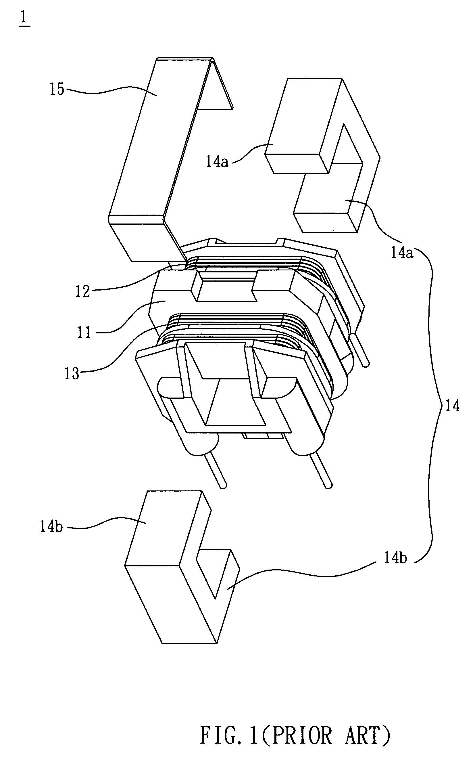
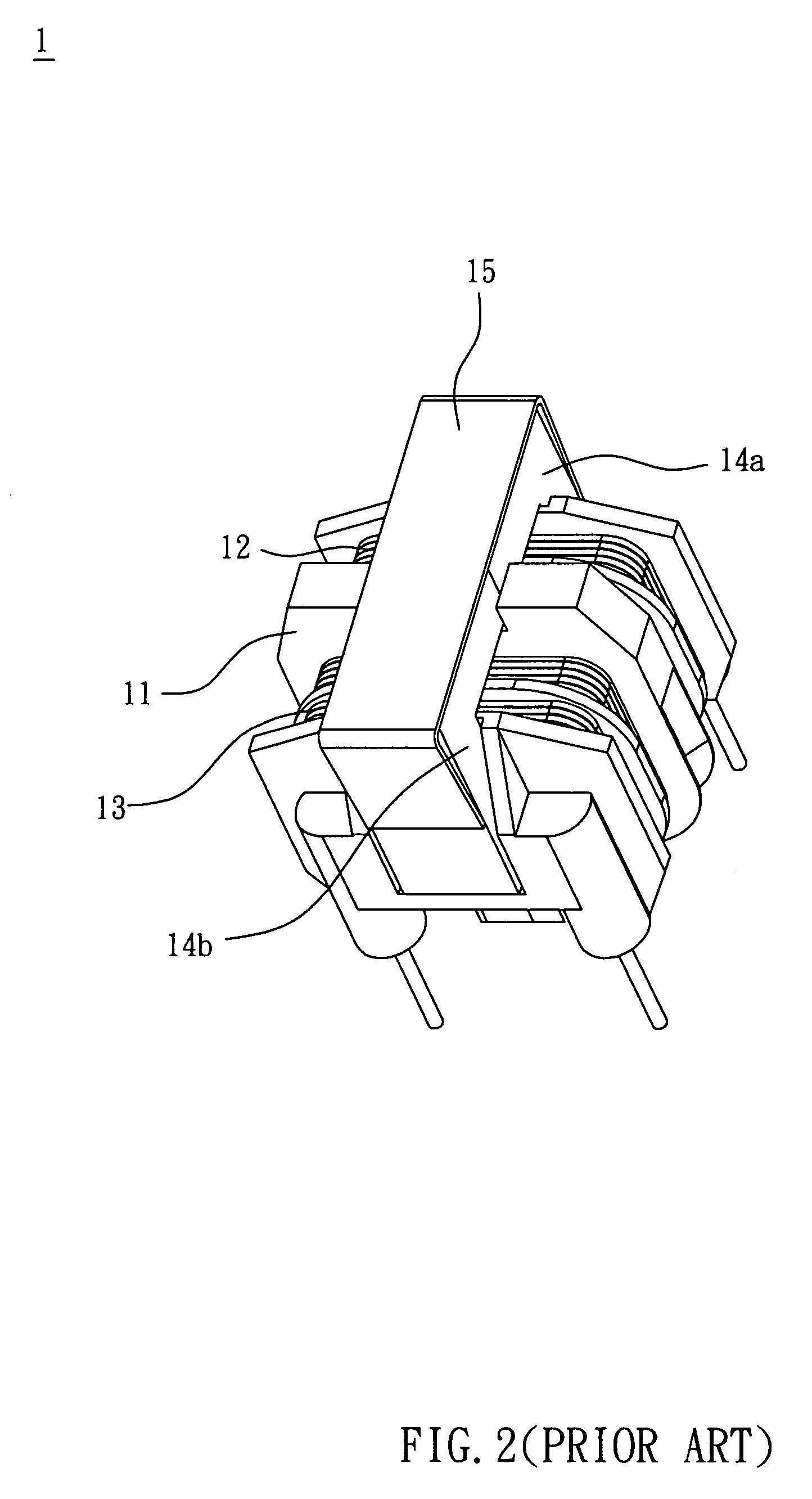
Although the inductor 1 can eliminate the electromagnetic element interference, the manufacturing cost is relatively increased because it is difficult to shape the magnetic element material into the bobbin in terms of the shaping technology.

Method used


Image

  • Inductor
  • Inductor
  • Inductor

Examples


Embodiment Construction

[0020]The present invention will be apparent from the following detailed description, which proceeds with reference to the accompanying drawings, wherein the same references relate to the same elements.

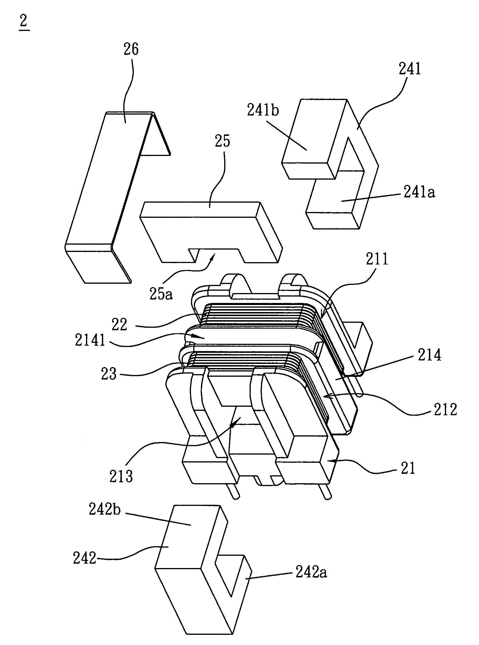
[0021]Referring to FIGS. 3 and 4, an inductor 2 according to an embodiment of the invention includes a bobbin 21, a first winding 22, a second winding 23, a core set 24 and a magnetic element 25.

[0022]In this embodiment, the bobbin 21 has a first winding area 211, a second winding area 212 and a partition 214, which is disposed between the first winding area 211 and the second winding area 212 and has a recess 2141 formed therein. The bobbin 21 further has a through hole 213 passing through the partition 214, the first winding area 211 and the second winding area 212. The material of the bobbin 21 of this embodiment is not particularly restricted, but is preferably a non-magnetic element material including, without limitation to, a plastic material.

[0023]The first winding 22 is wound ...


PUM

PropertyMeasurementUnit
winding areaaaaaaaaaaa
areaaaaaaaaaaa
magneticaaaaaaaaaa

Abstract

An inductor includes a bobbin, a first winding, a second winding, a core set and a magnetic element. The first and second windings are respectively wound around the bobbin and separated by a partition, which is formed on the bobbin and has a recess for accommodating the magnetic element. The core set has one portion passing through the bobbin and the other portion surrounding the bobbin, the first winding and the second winding. The magnetic element is connected with the one portion of the core set passing through the bobbin and is apart from the other portion of the core set outside the bobbin by a gap.

Description

CROSS REFERENCE TO RELATED APPLICATIONS[0001]This Non-provisional application claims priority under 35 U.S.C. §119(a) on Patent Application No(s). 095127664 filed in Taiwan, Republic of China on Jul. 28, 2006, the entire contents of which are hereby incorporated by reference.BACKGROUND OF THE INVENTION[0002]1. Field of Invention[0003]The invention relates to an inductor, and, in particular, to an inductor capable of filtering out a common-mode noise and a differential-mode noise simultaneously.[0004]2. Related Art[0005]Because a circuit used in an electronic apparatus, such as a power supply or a power transformer, frequently operates in a high-frequency switching environment, the electro-magnetic element interference (EMI) tends to occur and thus influences the operation of the electronic apparatus. The EMI can be classified into the radiated EMI and the conducted EMI according to a transfer method. The radiated EMI is directly transferred in an open space, while the conducted EMI ...

Claims


Application Information

Patent Timeline
Patent Type & Authority Patents(United States)
IPC IPC(8): H01F27/30H01F27/24
CPCH01F17/04H01F27/365H01F27/325H01F2017/0093H01F27/36H01F27/366
Inventor FANG, JUNG-CHANWU, CHEN-FENG
Owner DELTA ELECTRONICS INC
Learn More