Three-dimensional image display

a three-dimensional image and display technology, applied in the field of three-dimensional image display, can solve the problems of high manufacturing cost, inconvenient viewing for stereoscopic viewers, and not allowing three-dimensional display in a true sens

Inactive Publication Date: 2008-11-04
HIDEYOSHI HORIMAI
View PDF23 Cites 123 Cited by
  • Summary
  • Abstract
  • Description
  • Claims
  • Application Information

AI Technical Summary

Benefits of technology

[0046]In this three-dimensional image display, the two-dimensional image forming means emits light carrying information on a plurality of two-dimensional images to form a plurality of two-dimensional images, and the three-dimensional image forming means projects the light emitted by the two-dimensional image forming means in different directions in accordance with the positions of incidence, which results in projection of the plurality of two-dimensi

Problems solved by technology

Among the above techniques, the above-described stereoscopic viewers are inconvenient for a viewer because he or she must wear dedicated eyeglasses and are not suitable for observation for a long time because they present unnatural images which are likely to give fatigue.
However, techniques for stereoscopic views of this type only present pseudo-stereoscopic display utilizing parallax between left and right eyes and do not allow three-dimensional display in a true sense.
Further, since those are techniques utilizing parallax, a change of a view point only results in a view of the same image with a stereographic sense (a sense of depth), and a side of an object will not appear even if the viewer moves the head to look at the object from left and right sides thereof.
The above-described technique for presenting stereoscopic display utilizing holography involves a large scale ap

Method used


Image

  • Three-dimensional image display
  • Three-dimensional image display
  • Three-dimensional image display

Examples


first embodiment

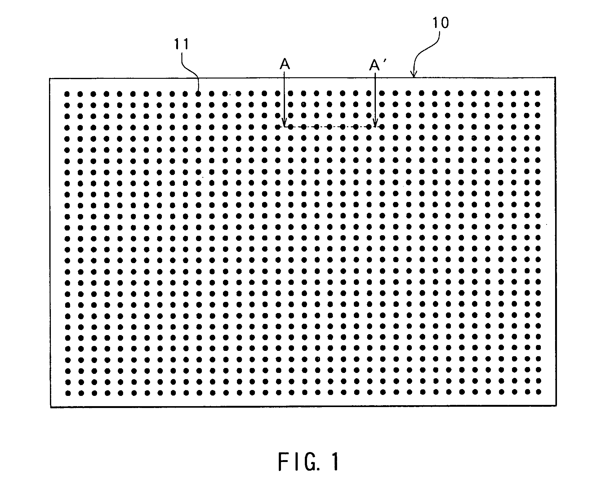
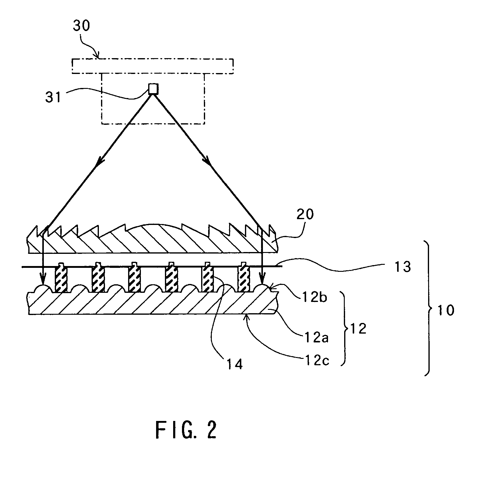
[0146]FIG. 1 shows a frontal structure of a three-dimensional screen forming a part of a three-dimensional image display according to the present embodiment. FIG. 2 shows a sectional structure of the three-dimensional image display taken along the line A-A′ in FIG. 1. FIG. 3 is an enlarged view of a part of the sectional structure of the three-dimensional display screen shown in FIG. 2. As shown in FIG. 1, the three-dimensional display screen 10 has screen dots 11 arranged in the form of a matrix at constant intervals in each of the horizontal direction (lateral direction of the figure) and the vertical direction (vertical direction of the figure). As shown in FIGS. 2 and 3, the three-dimensional display screen 10 has: a multiplicity of light diffusing elements 12 formed of a transparent material that allows visible light to pass through with substantially no loss and arranged in the form of a matrix; and liquid crystal display elements (hereinafter referred to as “LCDs”) 13 provide...

second embodiment

[0186]A second embodiment of the invention will now be described.

[0187]FIG. 21 shows a schematic configuration of a three-dimensional image display according to a second embodiment of the invention. The three-dimensional image display has an LCD panel 61 formed by arranging a plurality of LCDs 60 in each of the horizontal and vertical directions and has a three-dimensional display screen 63 which has a configuration including a plurality of pinhole elements 62 and which is provided in parallel with the LCD panel 61 in a face-to-face relationship with the same. A diffusing plate and a light source portion which are not shown are provided behind the LCD panel 61. Although FIG. 21 shows the LCD panel 61 and three-dimensional screen 63 as being spaced at a considerable interval for convenience, they may be provided closer. The LCD panel 61 corresponds to the “two-dimensional image forming element” of the invention.

[0188]Each of the LCDs 60 is formed by arranging H pixels in the horizont...

third embodiment

[0201]A third embodiment of the invention will now be described.

[0202]While the three-dimensional image display of the second embodiment can achieve high definition in representing an image to be viewed by the viewer Q at each view point, the angular resolution is lower than that in the first embodiment because the pinhole elements 62 of the three-dimensional display screen 63 must be arranged at a large pitch D (FIG. 21), which can result in a phenomenon that a stereoscopic image appears or disappears each time the viewer Q changes the view point. In order to eliminate such a problem, the present embodiment makes it possible to improve angular resolution. A detailed description on the embodiment will now be made with reference to FIGS. 24 through 28.

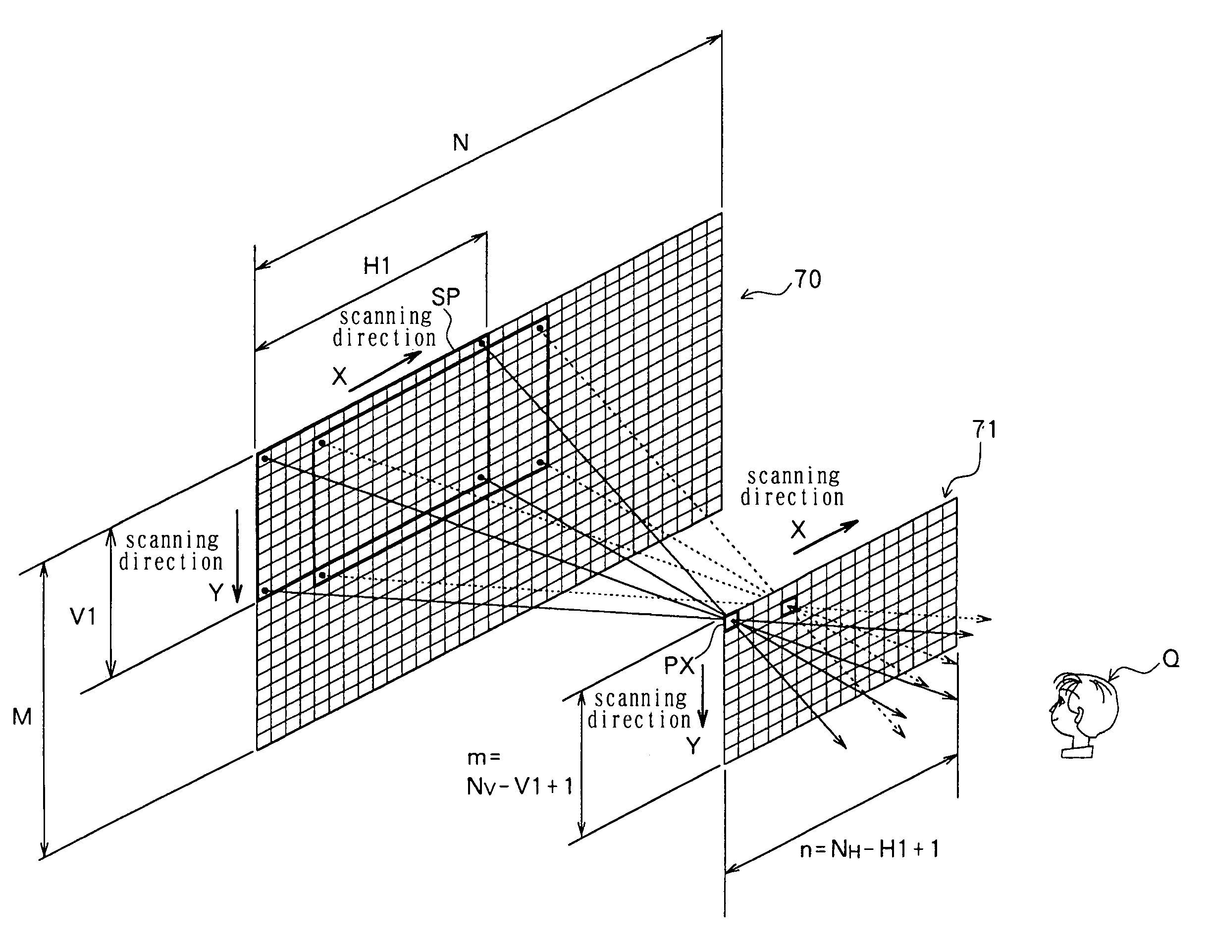
[0203]FIG. 24 shows a schematic configuration of a three-dimensional image display according to a third embodiment of the invention. The three-dimensional image display has: a picture LCD panel 70 including a multiplicity of pixels in t...


PUM


Abstract

The present invention provides a three-dimensional image display capable of presenting stereoscopic display in a true sense not only for a still image but also for a dynamic image without any need for a dedicated eyeglass or coherent light.
A multiplicity of screen dots (11) formed by LCDs which allows simple changes of the contents of an image are arranged on a three-dimensional display screen (10), and object images formed by the LCDs are projected in a space to form a multiplicity of point light source images (P) that form a three-dimensional image (R) to be displayed. A viewer (Q) can view the same as a stereoscopic image.

Description

TECHNICAL FIELD[0001]The present invention relates to a three-dimensional image display capable of displaying a stereoscopic image in a space.BACKGROUND ART[0002]Various proposals have recently been made on techniques for displaying a stereoscopic image as a result of the progress of optical technologies. One of such techniques is two-glass type three-dimensional viewers such as IMAX THEATER (trademark) capable of presenting stereoscopic display to a user who wears dedicated eyeglasses to see an image formed by an image for the left eye and an image for the right eye in an overlapping relationship. This apparatus can present stereoscopic display in the form of a stereogram utilizing parallax between left and right eyes.[0003]Stereoscopic display is also performed with holography utilizing coherent light from a laser or the like. This technique is to display a stereoscopic image by forming a hologram on a dry plate or the like using object light and reference light in advance and by ...

Claims


Application Information

Patent Timeline
IPC IPC(8): G09G3/00G03B21/00G09G5/00G02B30/27G03B35/18
CPCG02B3/005G02B3/0062G02B3/0068G02B27/2214G02B27/2292G03B35/18G02B30/56G02B30/27
Inventor HIRIMAI, HIDEYOSHI
Owner HIDEYOSHI HORIMAI
Why Eureka
Try Eureka