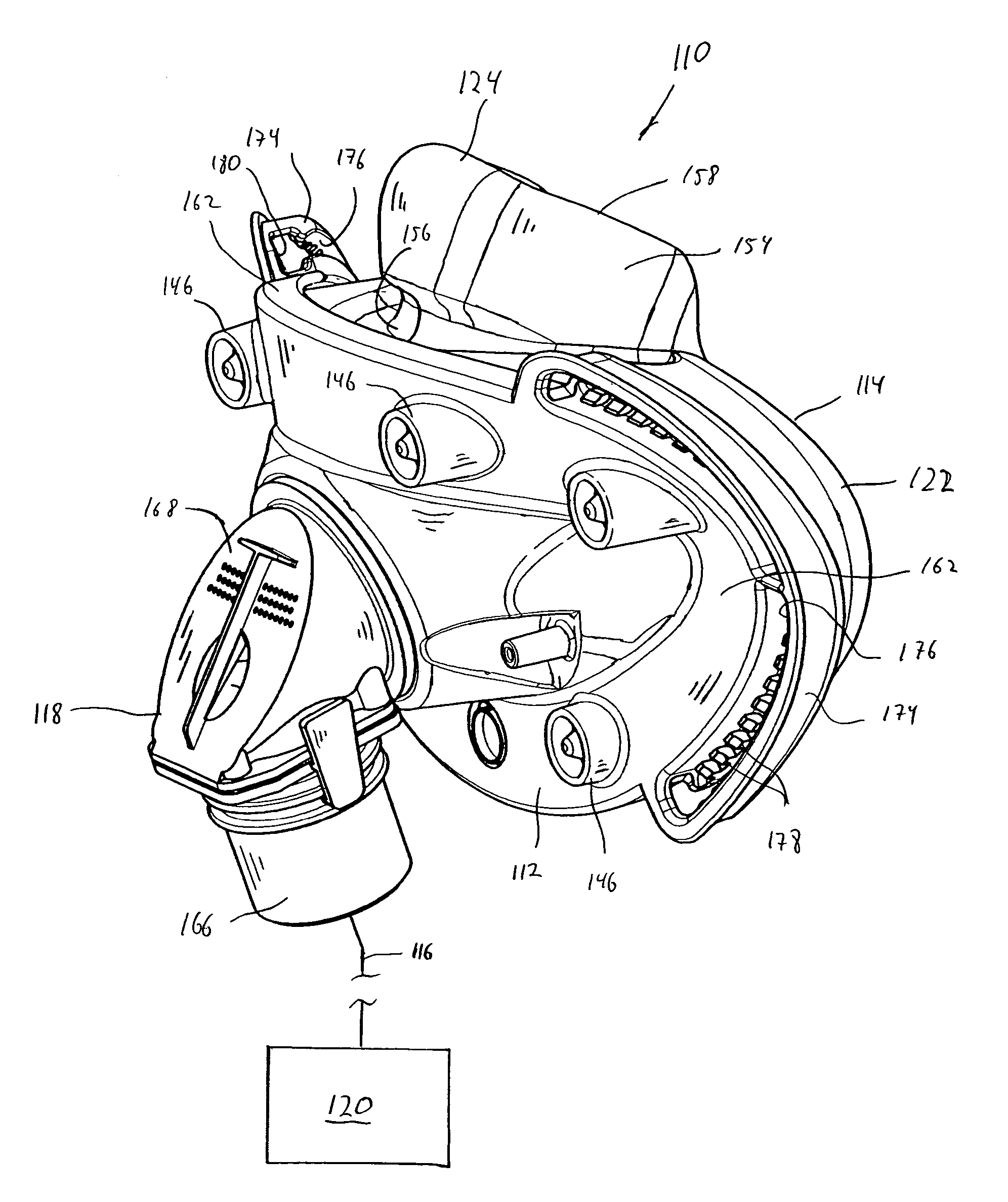
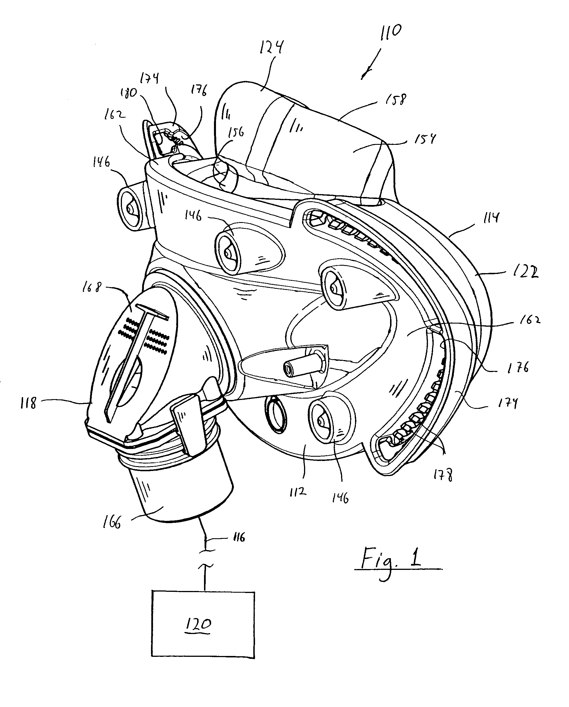
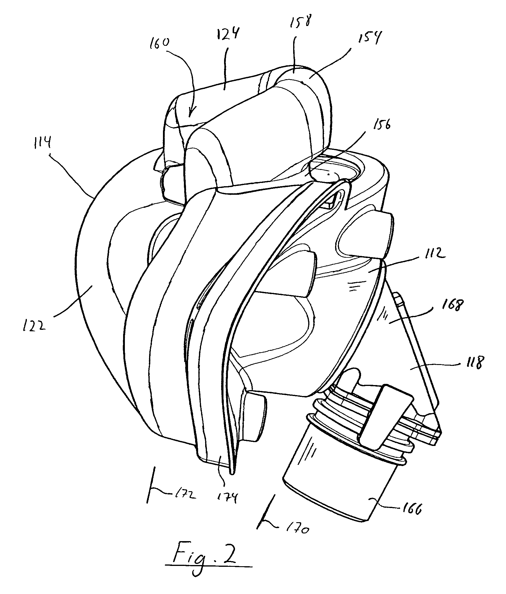
Full face respiratory mask with integrated nasal interface
a full-face mask and nasal interface technology, applied in the field of full-face masks, can solve the problems of less comfortable and intrusive, less comfortable for users, heavy and bulky, etc., and achieve the effect of reducing the variation among the surfaces, and reducing the complexity of sealing
- Summary
- Abstract
- Description
- Claims
- Application Information
AI Technical Summary
Benefits of technology
Problems solved by technology
Method used
Image
Examples
first embodiment
[0062]The present invention contemplates that the faceplate and the seal member, including the oral cushion portion and the nasal interface portion, can have a variety of configurations. Many of these possible alternative configurations are illustrated in the attached figures and described below. A first embodiment for the faceplate and seal member according to the principles of the present invention shown in FIGS. 1-5 will now be described.
[0063]As can perhaps best be seen in FIGS. 4-5, oral cushion portion 122 is a gas-filled cushion having a U-shaped cross section. An exemplary embodiment of a gas-filled cushion suitable for use in the present invention is disclosed in co-pending provisional U.S. patent application Ser. No. 11 / 599,133, (“the '133 application”) the contents of which are incorporated herein by reference.
[0064]Oral cushion portion includes a curved portion 126, an inner side wall 128, an outer side wall 30, and an interior 132. Oral cushion portion 122 is preferably...
eighth embodiment
[0091]FIG. 27 illustrates patient interface assembly 900 that includes a headgear 902 and a patient interface 904. Patient interface 904 corresponds to patient interface 110 except that the nasal interface portion includes a pair of nasal pillows rather than a cup-shaped cushion. Headgear 902 includes a pair of straps 906 and 908 that extend around the back of the user's head and are joined together at strip portion 909. A coupling member 910 is coupled to strip portion 909 such that the coupling member is selectively moveable along the strip portion as indicated by arrow A. The position of coupling member 910 on strip portion 909 can be controlled by a locking mechanism (not shown) or it can be left uncontrolled, so that the coupling member seeks the optimum position on the strip portion for each user. A connecting strap 912 connects coupling member 910 to a headgear clip 914.
[0092]Headgear clip 914 corresponds to the headgear clip shown in the '133 application and includes a porti...
ninth embodiment
[0093]FIG. 28 illustrates a patient interface assembly 940 that includes a headgear 942 and a patient interface 944. Patient interface 944 corresponds to patient interface 310. In this embodiment, headgear straps 946 are coupled to the faceplate of the patient interface using a hook clip 340, as discussed above with respect to the embodiment illustrated in FIGS. 8-14. Hook clip 340 can be located in any pair of openings 360 to suit the particular needs / desires of the user. In addition to straps that wrap around the back of the head, headgear 942 includes a strap 948 that wraps over the top of the head. An optional chin strap is shown by dashed lines 950. The present invention also contemplates providing a cap in addition to, or in place of the headgear straps. An example of such a cap is disclosed in U.S. Pat. No. 6,805,117.
PUM
 Abstract
Description
Claims
Application Information
 - R&D
- Intellectual Property
- Life Sciences
- Materials
- Tech Scout
- Unparalleled Data Quality
- Higher Quality Content
- 60% Fewer Hallucinations
Browse by: Latest US Patents, China's latest patents, Technical Efficacy Thesaurus, Application Domain, Technology Topic, Popular Technical Reports.
© 2025 PatSnap. All rights reserved.Legal|Privacy policy|Modern Slavery Act Transparency Statement|Sitemap|About US| Contact US: help@patsnap.com


