Tongs with encapsulated locking mechanism

a technology of locking mechanism and locking device, which is applied in the field of household kitchen tools, can solve the problems of inability to recognize the advantages of such a design possibility, inconvenient to have two different tongs to handle these tasks, and inability to have a locking device with a locking mechanism, etc., and achieves the effect of adding structural and operating advantages

Active Publication Date: 2008-11-11
HELEN OF TROY LIMITED
View PDF16 Cites 24 Cited by
  • Summary
  • Abstract
  • Description
  • Claims
  • Application Information

AI Technical Summary

Benefits of technology

[0005]There is disclosed herein an improved kitchen utensil which avoids the disadvantages of prior devices while affording additional structural and operating advantages.
[0006]In an embodiment there is provided a kitchen utensil, specifically a pair of tongs, comprising a first arm having a workpiece engaging end and a pivot end, and a second arm having a workpiece engaging end and a pivot end, wherein the first and second arms are pivotally connected together proximate their respective pivot ends by a pivot pin to allow pivoting of the first and second arms to all points within a range from an open position to a close position. A biasing member is positioned to engage and bias the first and second arms to the open position, and a sliding locking plate having a slot through which the pivot pin passes to allow movement of the locking plate between a first position and a second position, and a body adjacent the slot such that the body engages the pivot ends of the first and second arms when in the first position to lock the arms in a close position. Finally, a handle encapsulating and coupled to the locking plate protects the locking mechanism and provides a greater ease of use.

Problems solved by technology

However, it is sometimes inconvenient to have two different tongs to handle these tasks, when one pair could easily be equipped to operate properly for both.
Those skilled in the art have failed to recognize the advantages of such a design possibility.
However, such locking devices are sometimes cumbersome, easily jammed, or too easily accidentally unlocked when washed and / or stored.

Method used


Image

  • Tongs with encapsulated locking mechanism
  • Tongs with encapsulated locking mechanism
  • Tongs with encapsulated locking mechanism

Examples


Embodiment Construction

[0017]While this invention is susceptible of embodiments in many different forms, there is shown in the drawings and will herein be described in detail a preferred embodiment of the invention with the understanding that the present disclosure is to be considered as an exemplification of the principles of the invention and is not intended to limit the broad aspect of the invention to embodiments illustrated.

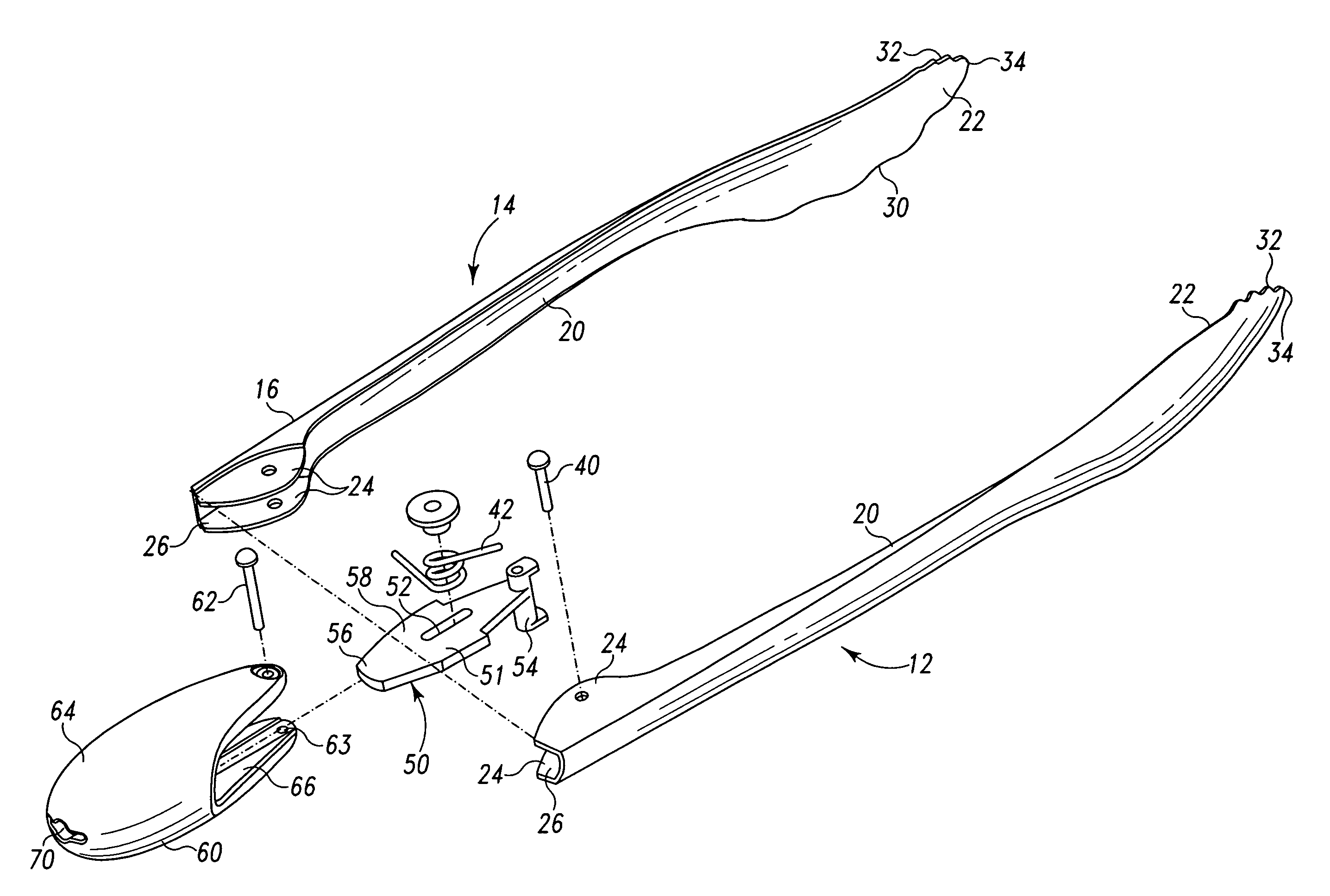
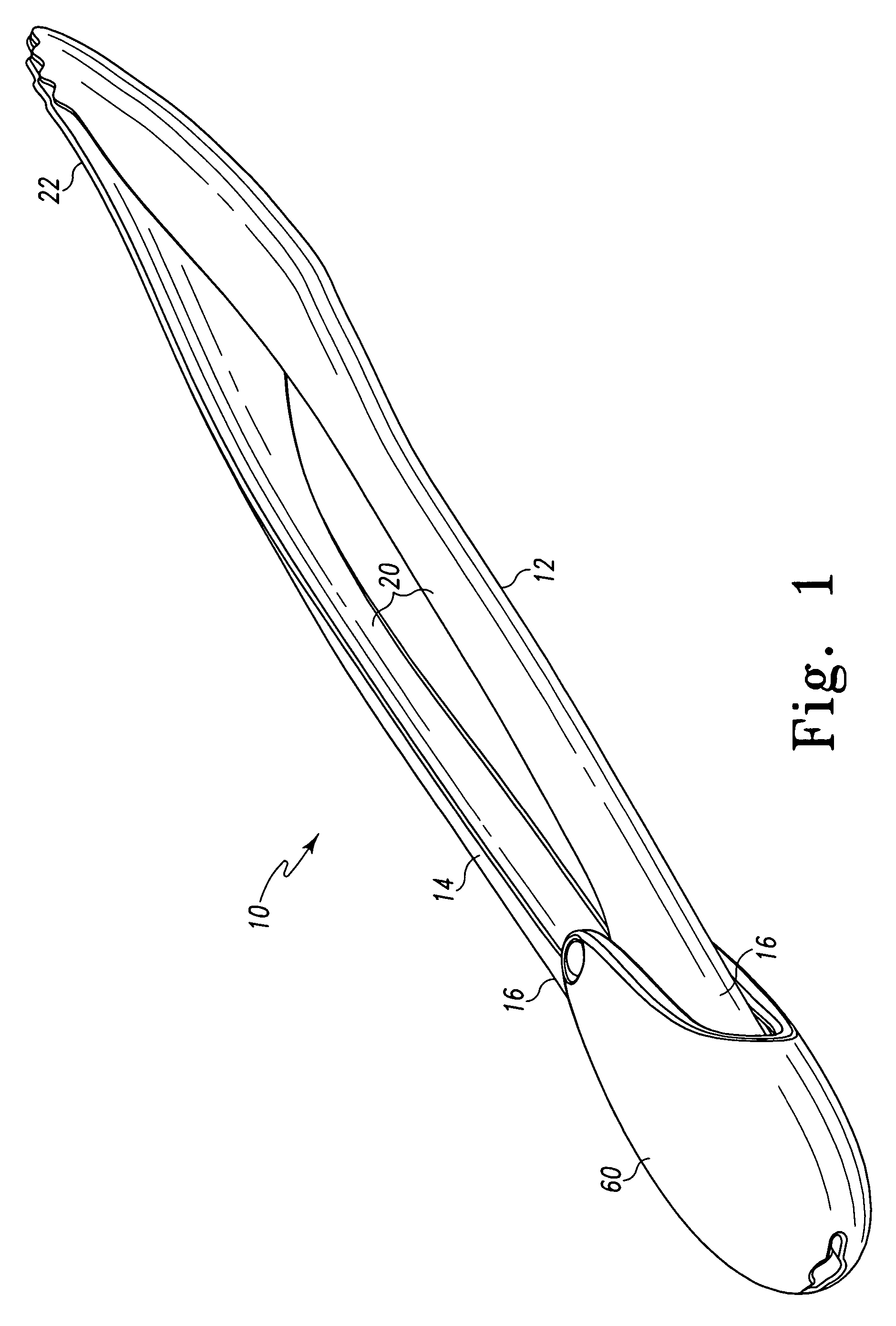
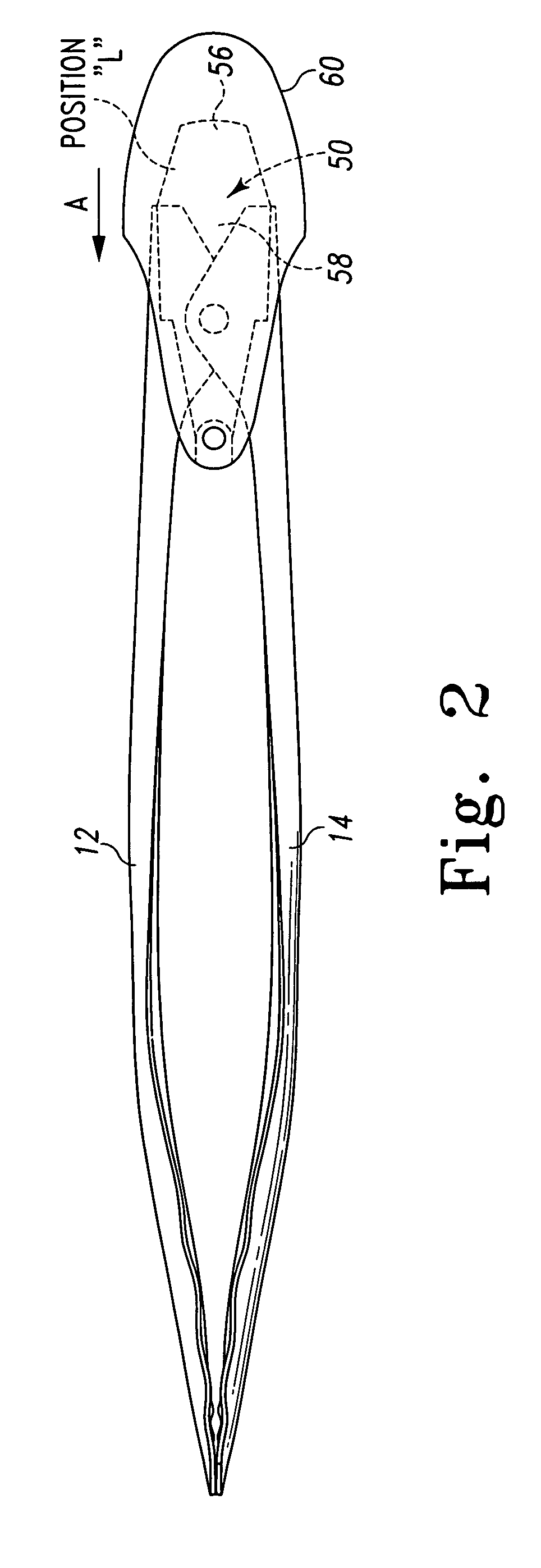
[0018]Referring to FIGS. 1-5, there is illustrated a kitchen utensil, namely tongs, generally designated by the numeral 10. The tongs 10 have a first arm 12 pivotally connected to a second arm 14 at a pivot point. Each arm is comprised of a pivot end 16, a body portion 20 and a workpiece engaging or grasping end 22.

[0019]As shown in FIG. 4, the pivot end 16 of each arm 12, 14 has a substantially U-shaped cross section with a small lobe 24 on each side of channel 26 to facilitate connection. The width of the two channels 26 are such that one fits into the span of the other as the l...


PUM


Abstract

A pair of locking kitchen tongs for use in handling food items and the like is disclosed. The tongs have a pair of rigid steel arms each having a workpiece engaging or grasping end, a body portion and a pivot end from which the arms are pivotally connected together. The grasping ends are preferably scalloped along one edge, for handling relatively large items, and serrated (i.e., fine-toothed) along another edge, for handling of smaller or fine items. A bulbous, tear-shaped body made from a rigid, non-metal material encapsulates the pivot ends of the two arms as they are pivotally connected together to permit movement between an open position and a closed position. Also within and coupled to the encapsulating body is a sliding locking plate. The locking plate has a body defining a slot which allows the locking plate to slide between a locked position, maintaining the arms in their closed position, and an unlocked position, allowing them free pivoting movement.

Description

BACKGROUND OF THE INVENTION[0001]This application relates to household kitchen tools. In particular, this application relates to hand-held tongs of the type used to handle and serve food. The application relates most specifically to hand-held tongs having a locking mechanism.[0002]Tongs of the common form include a pair of pivoting arms, usually made of a metal or a hard plastic, either with or without similarly or differently contoured ends for grasping food and the like. The contoured ends are typically flared to allow for manipulation of relatively broad foods, such as, for example, burgers, bratwurst, bread rolls, fish fillets, pastries and the like. Alternatively, the tongs may be smaller in size with a serrated edge for grasping of relatively small or narrow goods, such as, for example, ice cubes, olives, carrot sticks, garnishes and such. However, it is sometimes inconvenient to have two different tongs to handle these tasks, when one pair could easily be equipped to operate ...

Claims


Application Information

Patent Timeline
Patent Type & Authority Patents(United States)
IPC IPC(8): A47G21/10A47J43/28
CPCA47J43/283G06Q40/00
Inventor YAMANAKA, SHUNJIOGATA, HISATOKANEKO, EUGENE
Owner HELEN OF TROY LIMITED
Why Eureka
Try Eureka