Leaned centrifugal compressor airfoil diffuser

Active Publication Date: 2008-11-11
PRAXAIR TECH INC
View PDF16 Cites 21 Cited by
  • Summary
  • Abstract
  • Description
  • Claims
  • Application Information

AI Technical Summary

Problems solved by technology

Recently however, due to increased competitiveness in the process industry, centrifugal compressor operating ranges are being challenged to increase beyond the existing ranges of the present two-dimensional diffuser configurations.

Method used


Image

  • Leaned centrifugal compressor airfoil diffuser
  • Leaned centrifugal compressor airfoil diffuser
  • Leaned centrifugal compressor airfoil diffuser

Examples


Embodiment Construction

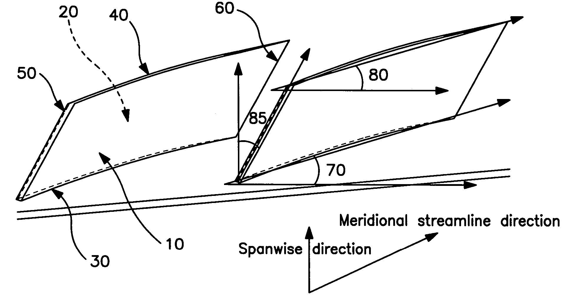
[0017]In general the invention comprises an improved low solidity airfoil diffuser for a centrifugal compressor where each blade has a lean angle greater than zero. The diffuser may be of the variable stagger type, also known as a twisted diffuser, wherein the hub stagger angle is different from the shroud stagger angle for each blade, or may be of the pure lean type where the hub stagger angle is the same as the shroud stagger angle for each blade.

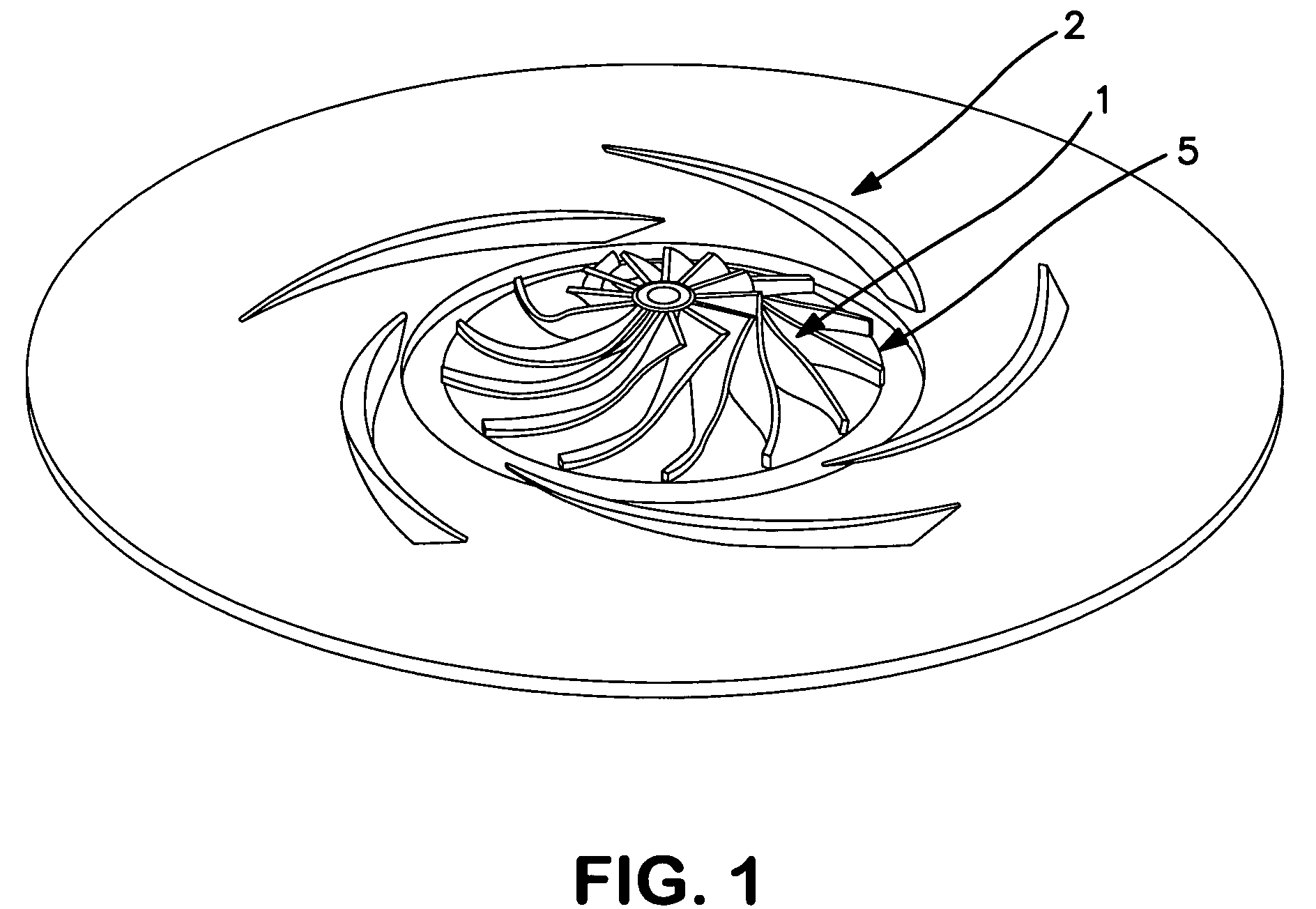
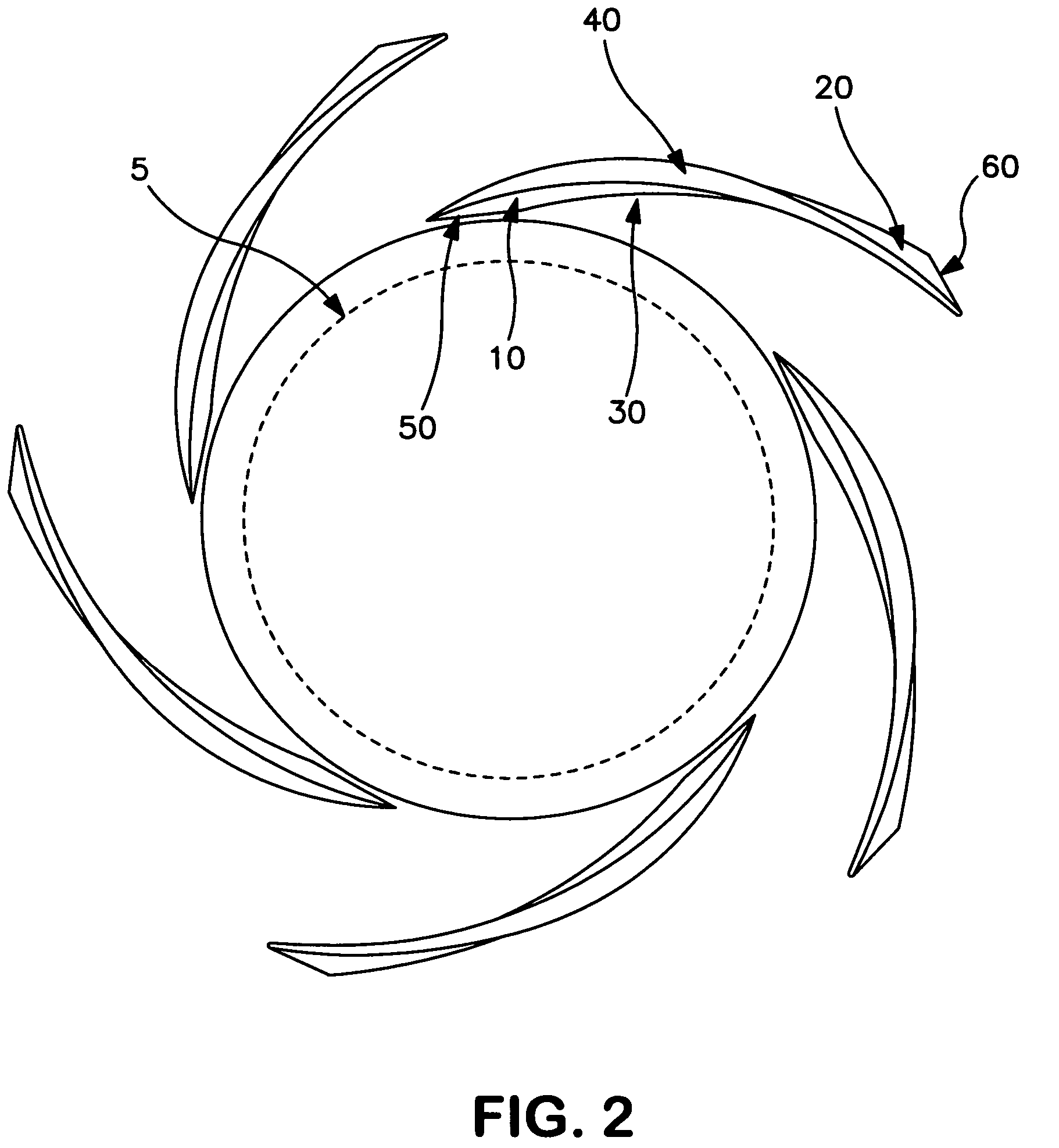
[0018]The invention will be described in greater detail with reference to the Drawings. FIG. 1 shows a centrifugal compressor impeller 1 with a diffuser 2, which may be a variable stagger diffuser as shown in FIG. 2 or a pure lean diffuser as shown in FIG. 3, with a more detailed view of the diffuser blade lean and twist shown in FIG. 4. In the Drawings 5 identifies the impeller outer diameter, 10 is the diffuser blade pressure surface, 20 is the diffuser blade suction surface, 30 is the diffuser blade hub, 40 is the diffuser blade shroud...


PUM


Abstract

A low solidity vaned airfoil diffuser for a centrifugal compressor wherein each blade has a lean angle greater than zero and wherein the hub stagger angle may be the same as or may be different from the shroud stagger angle for each blade.

Description

TECHNICAL FIELD[0001]This invention relates generally to centrifugal compressors and, more particularly, to centrifugal compressors for use in cryogenic rectification systems such as the cryogenic rectification of air to produce atmospheric gases such as oxygen, nitrogen,and argon.BACKGROUND ART[0002]A centrifugal compressor employs a wheel or impeller mounted on a rotatable shaft positioned within a stationary housing. The wheel defines a gas flow path from the entrance to the exit. Low solidity airfoil diffusers have been used successfully as efficient and compact dynamic pressure recovery devices in industrial centrifugal compressor stages. Typically such diffusers have a cascade of two-dimensional airfoil blades or vanes distributed circumferentially at close proximity to the impeller exit. The fundamental characteristic of this type of diffuser is the lack of a geometrical throat that permits it to increase the operating range without the risk of flow choking. This type of diff...

Claims


Application Information

Patent Timeline
Patent Type & Authority Patents(United States)
IPC IPC(8): F04D29/44
CPCF04D29/444F05D2250/52F04D29/44
Inventor ABDELWAHAB, AHMEDBAKER, ROBERT LEROYGERBER, GORDON J.
Owner PRAXAIR TECH INC
Why Eureka
Try Eureka