Automatic static grounding device for electrical components

a static grounding device and electrical component technology, applied in the direction of electrostatic charges, basic electric elements, electrical apparatuses, etc., can solve the problems of static charge being dangerous and electric components may retain static charges

Active Publication Date: 2008-11-11
EATON INTELLIGENT POWER LTD
View PDF0 Cites 10 Cited by
  • Summary
  • Abstract
  • Description
  • Claims
  • Application Information

AI Technical Summary

Problems solved by technology

There is a danger, however, that the electrical component may retain a static charge after the electrical component has been disconnected from the voltage source.
This static charge can be dangerous if not discharged prior to the time a person contacts the electrical component.

Method used


Image

  • Automatic static grounding device for electrical components
  • Automatic static grounding device for electrical components
  • Automatic static grounding device for electrical components

Examples


Embodiment Construction

[0012]As used herein, a “roll-out electrical component” is an electrical component such as, but not limited to, a voltage transformer, control power transformer, and fuses.

[0013]As used herein, directional terms, e.g., “above,”“below,”“upper,”“lower,” etc., are used for convenience relative to the Figures and are not intended to limit the claims.

[0014]As used herein, “coupled” means a link between two or more elements, whether direct or indirect, so long as a link occurs.

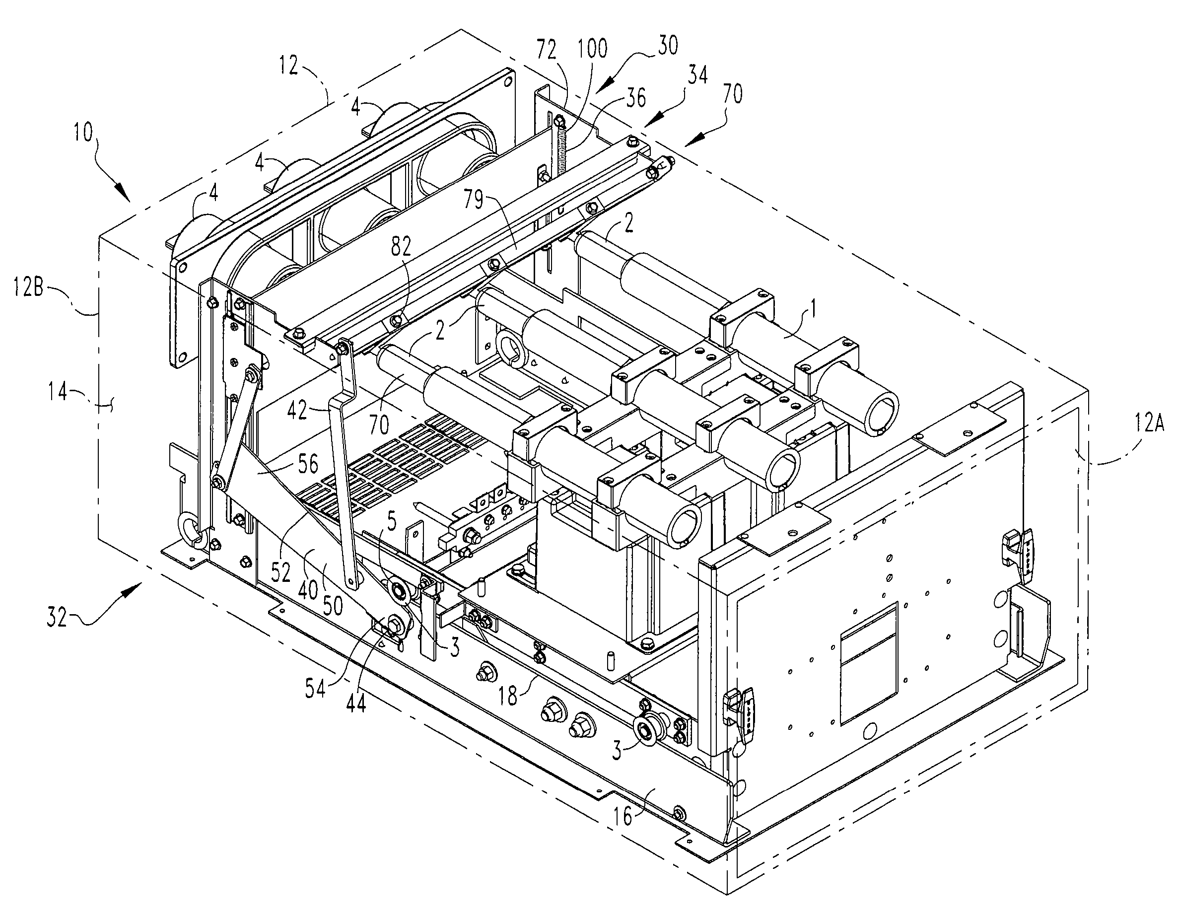
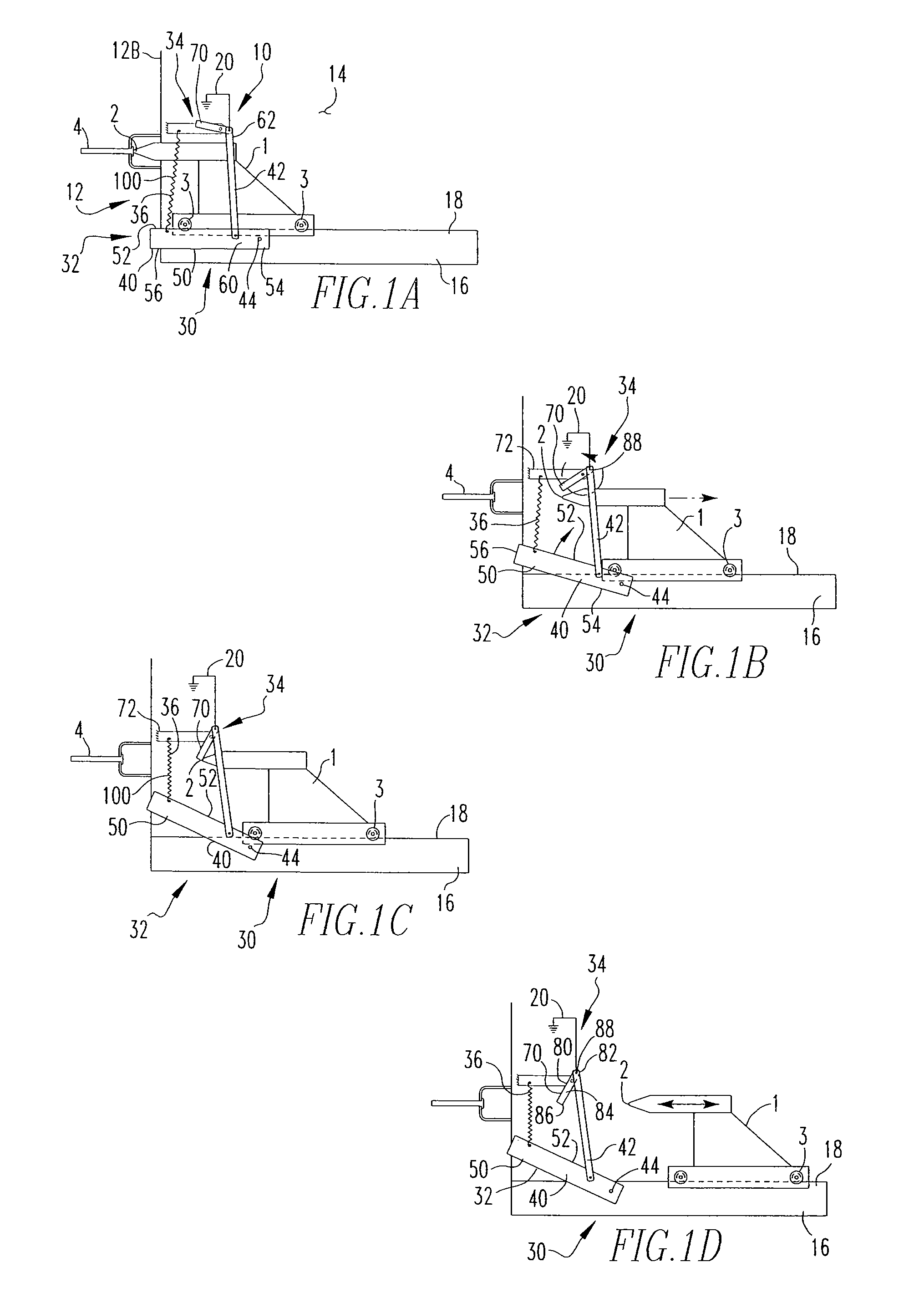
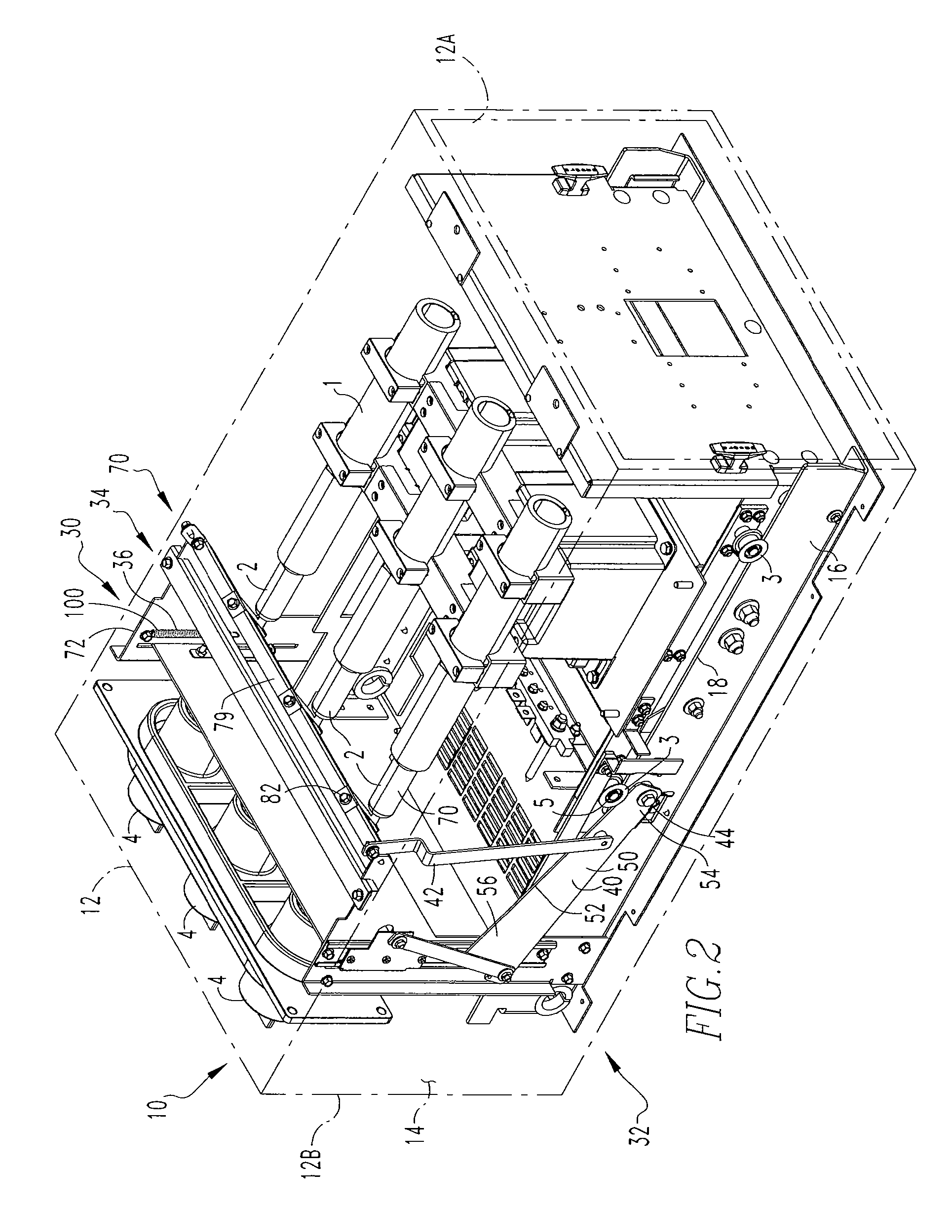
[0015]As shown in FIGS. 1A-1D and 2, a roll-out electrical component 1 includes at least one contact 2 structured to be coupled to a voltage source and a plurality of wheels 3 structured to engage the housing assembly rails 16, described below. As further described below, one wheel 3, preferably a wheel 3 adjacent to the back sidewall 12B, described below, has an extended axle 5 (FIG. 3), or another extension extending generally parallel to the axle. The roll-out electrical component 1 is structured to be removably ...


PUM


Abstract

A grounding device for a roll-out electrical component is provided. The grounding device includes an actuation assembly, a static grounding contact assembly, and a biasing device. The actuation assembly structured to be engaged / disengaged by a roll-out electrical component. The static grounding contact assembly has at least one static grounding contact member that is structured to move between a first position, wherein the static grounding contact member does not contact a roll-out electrical component at least one contact, and a second position, wherein the static grounding contact member contacts, and is in electrical communication with, the roll-out electrical component at least one contact. The static grounding contact assembly is coupled to the actuation assembly and responsive to the position of the roll-out electrical component. The biasing device is structured to bias the actuation assembly and the static grounding contact member to their respective first positions.

Description

BACKGROUND OF THE INVENTION[0001]1. Field of the Invention[0002]The present invention relates to a housing assembly for an electrical component and, more specifically, to a housing assembly having an automatic grounding device.[0003]2. Background Information[0004]Electrical components, especially high voltage components, are typically disposed in a protective housing assembly. The housing assembly includes a plurality of sidewalls defining an enclosed space in which the electrical component is disposed. An electrical conduit or other voltage source extends into the enclosed space. The housing assembly includes an external voltage source conductor that extends between, and is in electrical communication with, the voltage source and the electrical component. The housing assembly further includes a set of rails. The electrical component, typically, includes a set of wheels structured to engage the rails. Thus, the electrical component may be moved into, or out of, the enclosed space by...

Claims


Application Information

Patent Timeline
Patent Type & Authority Patents(United States)
IPC IPC(8): H05F3/00
CPCH02B11/24H02B11/28
Inventor PARKER, PAUL KIMBALLSMITH, JAMES EDWARDCOLBAUGH, PAUL ANTHONYCARDER, RONALD ALANBRANDT, DOUGLAS MICHAEL
Owner EATON INTELLIGENT POWER LTD
Why Eureka
Try Eureka