Optimizing order of error recovery steps in a disk drive

a disk drive and order technology, applied in the field of disk drives, can solve the problems of reducing the overall recovery time on average, not taking into account the execution time of each error recovery step, and based on the effectiveness of the order of error recovery steps,

Active Publication Date: 2008-11-11
WESTERN DIGITAL TECH INC
View PDF3 Cites 186 Cited by
  • Summary
  • Abstract
  • Description
  • Claims
  • Application Information

AI Technical Summary

Benefits of technology

[0010]In one embodiment, more than one of the error recovery steps may successfully recover a data sector. In another embodiment, the disk contro

Problems solved by technology

However, ordering the error recovery steps based on effectiveness does not take into account the execution time for each error recovery step.
For example, a highly effective error recovery step may have a significantly long execution time whereas a less effective error recovery step having a much shorter execution time may successfully recover an errant data sector under certain conditions, thereby reducing the overall recovery time on average if the less effective error recovery step is executed earlier in the error recovery

Method used


Image

  • Optimizing order of error recovery steps in a disk drive
  • Optimizing order of error recovery steps in a disk drive
  • Optimizing order of error recovery steps in a disk drive

Examples


Embodiment Construction

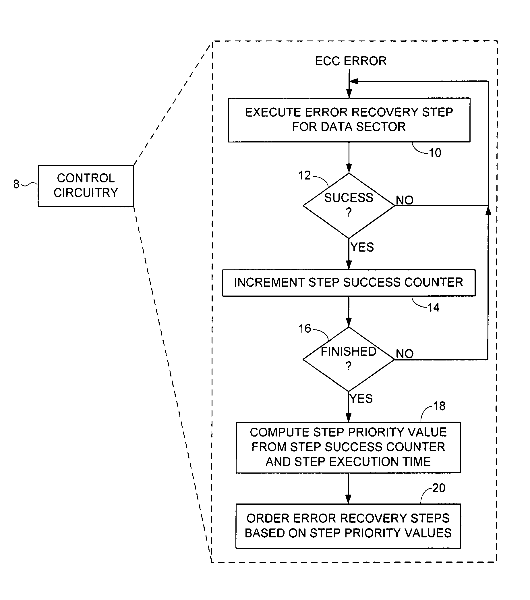
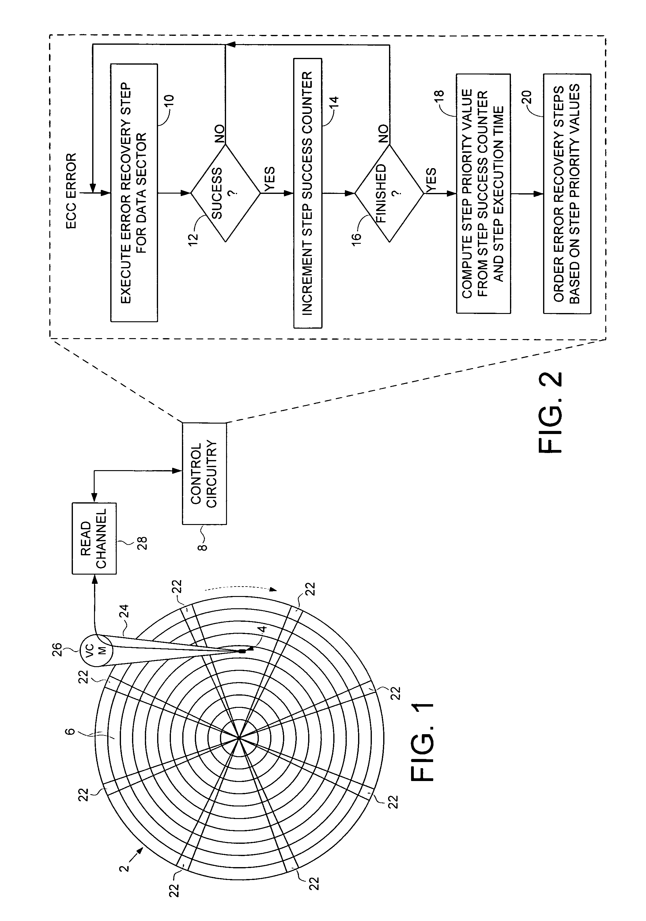
[0023]FIG. 1 shows a disk drive according to an embodiment of the present invention comprising a disk 2 and a head 4 actuated over the disk 2, wherein the disk 2 comprises a plurality of tracks 6 and each track 6 comprises a plurality of data sectors. The disk drive further comprises disk control circuitry 8 for executing an error recovery procedure comprising a plurality of error recovery steps, wherein each error recovery step having an execution time. The disk control circuitry 8 maintains a plurality of step success counters each corresponding to one of the error recovery steps. The disk control circuitry 8 executes the flow diagram of FIG. 2 wherein if a data sector cannot be recovered using the ECC circuitry at step 10a plurality of the error recovery steps are executed for a plurality of the data sectors, wherein if an error recovery step successfully recovers one of the data sectors at step 12, at step 14 the corresponding step success counter is incremented. When finished e...


PUM


Abstract

A method is disclosed for ordering error recovery steps of an error recovery procedure executed by a disk drive, wherein each error recovery step having an execution time. The disk drive comprises a disk having a plurality of tracks, wherein each track comprises a plurality of data sectors. A plurality of step success counters are initialized, wherein each counter corresponds to one of the error recovery steps. A plurality of the error recovery steps are executed, wherein if an error recovery step successfully recovers one of the data sectors the corresponding step success counter is incremented. A step priority value is computed for each error recovery step in response to the step success counter and execution time for each step. The error recovery steps are then ordered in response to the step priority values.

Description


Claims


Application Information

Patent Timeline
Owner WESTERN DIGITAL TECH INC
Why Eureka
Try Eureka