Plug valve having a seal boss

a technology of sealing boss and plug valve, which is applied in the direction of multiple way valve, transportation and packaging, mechanical equipment, etc., can solve the problems of manufacturers having to spend extra time and money, and achieve the effect of limiting the deformation of the elastomeric seal and enhance the metal-to-metal sealing of the inner sid

Active Publication Date: 2008-11-18
SPM OIL & GAS INC
View PDF20 Cites 28 Cited by
  • Summary
  • Abstract
  • Description
  • Claims
  • Application Information

AI Technical Summary

Benefits of technology

[0006]The fluid control valve of the present invention utilizes a rotatable plug valve member mounted in a fluid passage to control the flow of fluids. Two segments are placed on each side of the plug valve member within a recess located between the plug valve member and the body of the fluid passage. The outer surface of the segments includes an elastomeric seal and a metal annular boss. The elastomeric seal seals against the recess and exerts an inward force to enhance metal-to-metal sealing of the inner side of the segment with the plug. The annular boss contacts the recess to limit the deformation of the elastomeric seal within its groove.

Problems solved by technology

As such, manufacturers must spend extra time and money to achieve an exact fit.

Method used


Image

  • Plug valve having a seal boss
  • Plug valve having a seal boss
  • Plug valve having a seal boss

Examples


Embodiment Construction

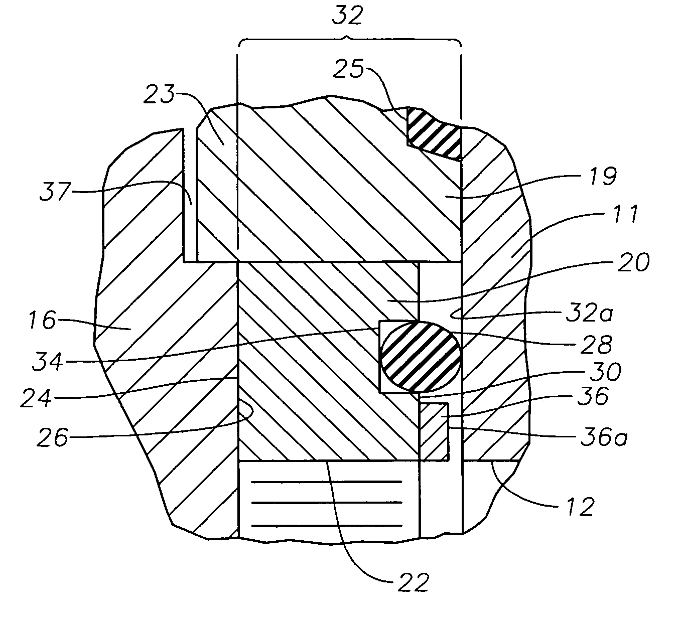
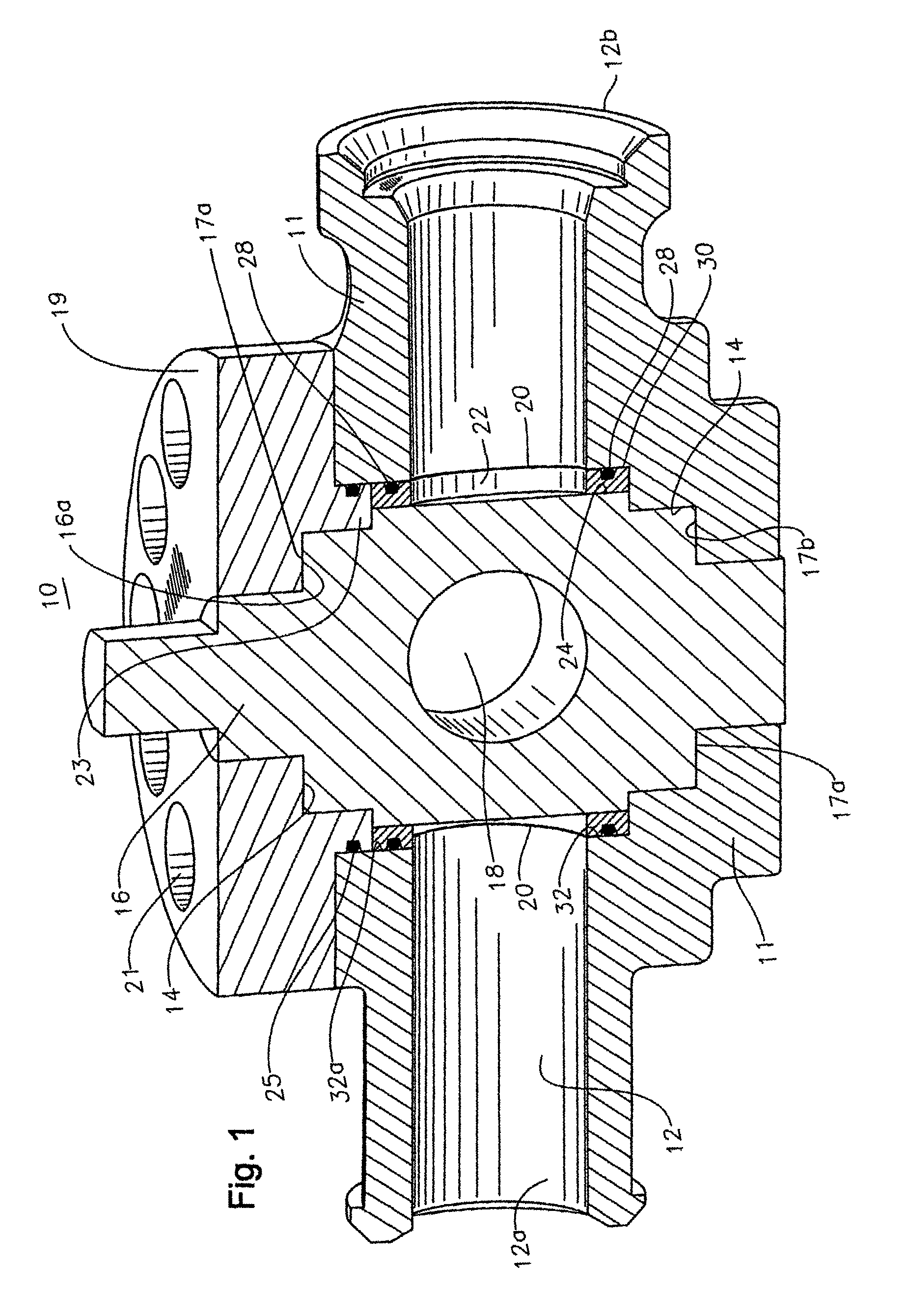
[0013]Referring to FIG. 1, a fluid control valve according to an embodiment of the present invention is illustrated. Fluid control valve 10 includes a housing 11 having a flow passage 12 extending therethrough, which allows various fluids to be transported. Flow passage 12 has two separate portions 12a and 12b, each of which may be an inlet or an outlet. For convenience, portion 12a is considered to be an upstream portion or inlet and portion 12b a downstream portion or outlet. Flow passage 12 is typically cylindrical.

[0014]Housing 11 contains a stepped cylindrical cavity 14 with an axis perpendicular to the axis of flow passage 12. Flow passage portions 12a, 12b intersect cavity 14. A cylindrical rotatable plug 16 fits within cavity 14. Plug 16 has a cylindrical passage 18 extending through it perpendicular to the axis of plug 16. Plug 16 is a 90 degree “ON / OFF” device, which can be rotated along its axis between an open position, wherein passage 18 aligns with flow passage 12, and...


PUM


Abstract

A fluid control valve utilizes a rotatable plug valve member mounted in a fluid passage to control the flow of fluids. Two segments are placed on each side of the plug valve member within a recess located between the plug valve member and the body of the fluid passage. The outer surface of the segments includes an elastomeric seal and metal annular boss, which acts as a stop to limit deformation of the seal when the valve is closed and under pressure.

Description

BACKGROUND[0001]1. Field of the Invention[0002]This invention relates in general to fluid control valves, such as used in oilfield workover applications and in particular to a plug valve having a metal-to-metal seal between a rotatable plug and a sealing segments.[0003]2. Description of the Prior Art[0004]In fluid control valves of the plug type, a rotatable, cylindrical plug with a transverse hole is mounted in a transverse opening of the fluid flow valve body. The rotation of the plug is achieved through the use of a rotatable stem, which allows the valve to move between a closed position, in which the plug valve prevents fluid flow through the flow passage, and an open position, in which the plug valve allows the fluid to flow.[0005]The plug is sealed by a pair of semi-cylindrical segments, which are placed in recesses formed between the transverse opening and the flow passages. Each segment has a hole that registers with one of the flow passages and is located between the plug v...

Claims


Application Information

Patent Timeline
Patent Type & Authority Patents(United States)
IPC IPC(8): F16K5/04
CPCF16K5/0464Y10T137/86871F16K5/0471
Inventor MATZNER, MARK D.
Owner SPM OIL & GAS INC
Why Eureka
Try Eureka