Tissue sensing adaptive radar imaging for breast tumor detection

a breast tumor and adaptive radar technology, applied in the field of breast tumor detection methods and apparatuses, can solve the problems of small risk of breast tumor induced in patients, undiagnosed lesion, and unknown limitations, and achieve the effect of small image contribution and large image contribution

Inactive Publication Date: 2008-11-18
UTI LLP
View PDF15 Cites 78 Cited by
  • Summary
  • Abstract
  • Description
  • Claims
  • Application Information

AI Technical Summary

Benefits of technology

[0010]Radar-based imaging methods may also be known as confocal microwave imaging (CMI). Reflections may be observed at a number of antennas located on the breast, and images may be created by summing the reflections or synthetically focusing these reflections. Synthetic focusing involves calculating the time-delay from each antenna to a focal point, and time-shifting and summing the recorded signals. If a tumor was located at the focal point, then reflections from the tumor add together, resulting in a large contribution to the image at that focal point location. With the focal point in normal tissues, reflections tend to add incoherently, resulting in a small contribution to the image. By scanning the focal point through the volume of interest and observing areas of strong reflection, tumor detection and localization is possible.

Problems solved by technology

While mammography is very sensitive to lesions in the breast, it has acknowledged limitations.
This is especially problematic for imaging women with dense breasts, which comprise a significant portion of the population.
Another limitation is that a lesion may not be immediately diagnosed via a single mammogram.
Every time a mammogram is taken, the patient incurs a small risk of having a breast tumor induced by the ionizing radiation properties of the X-rays used during the mammogram.
Also, the process is sometimes imprecise and, as a result, not cost-efficient.
However, about ten to fifteen percent of tumors of this size and most tumors below this size are not detected.
Further, many women find that undergoing a mammogram is a decidedly painful experience.
These limitations have generated interest in alternative breast imaging methods.
Ultrasound is often used to differentiate solid tumors from liquid cysts, but does not provide definitive information on whether a solid tumor is malignant or benign.
The uptake and washout of the contrast agent in the vicinity of the suspicious lesion is monitored, however it may be difficult to provide a definitive diagnosis as malignancies generally do not have behavior that is consistently and distinctly different than benign lesions.

Method used


Image

  • Tissue sensing adaptive radar imaging for breast tumor detection
  • Tissue sensing adaptive radar imaging for breast tumor detection
  • Tissue sensing adaptive radar imaging for breast tumor detection

Examples


Embodiment Construction

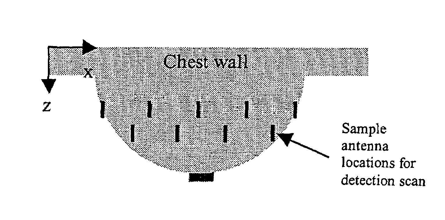
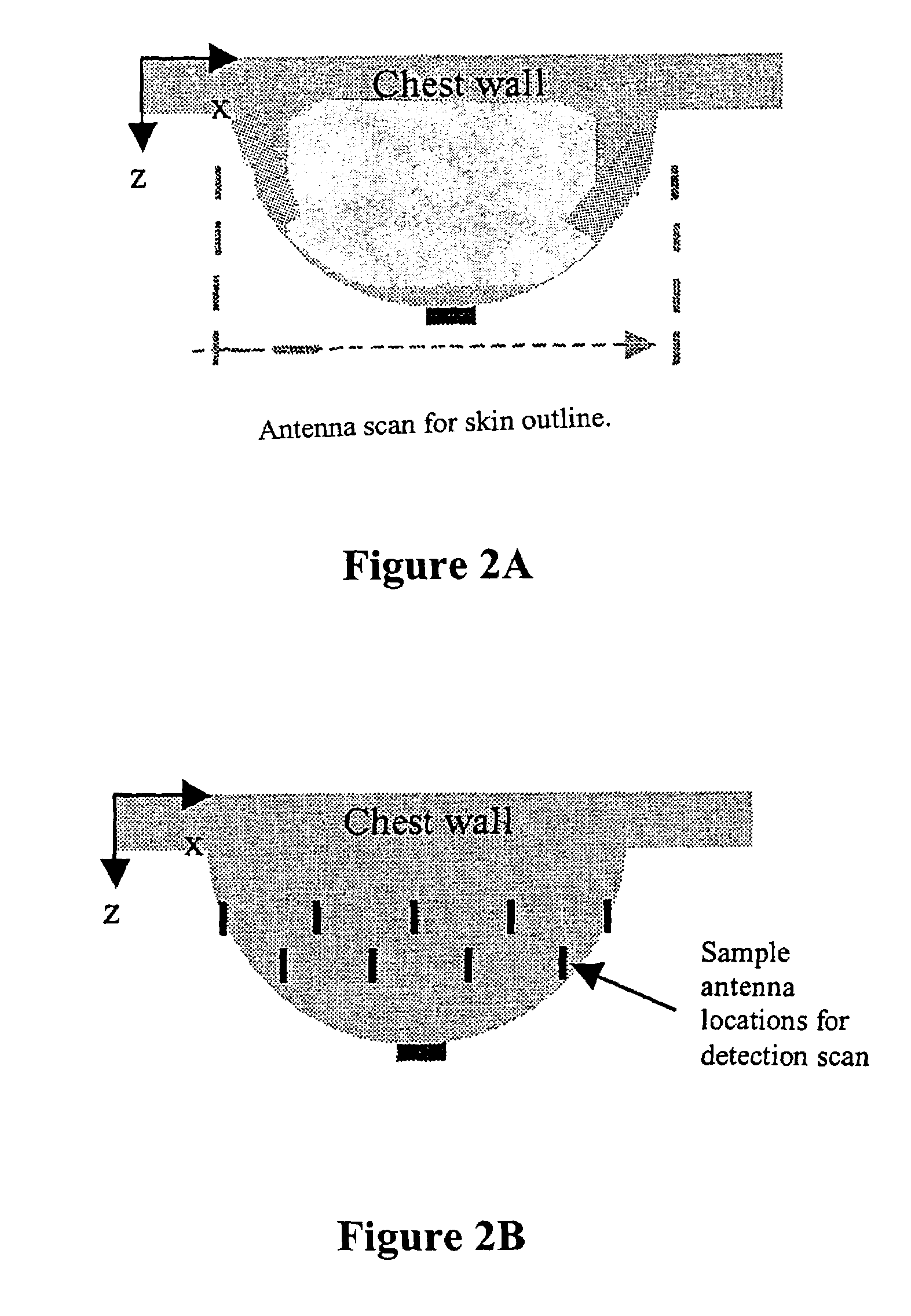
[0017]The present invention provides for a method and apparatus for tissue sensing adaptive radar imaging of breast tissue. When describing the present invention, all terms not defined herein have their common art-recognized meanings. As used herein, “microwave” means a comparatively short electromagnetic wave, especially one between about one millimeter and one meter in wavelength, and corresponding to a frequency range from 300 MHz to 300 GHz. The term “radar” refers to a method of detecting the presence and location of an object by detecting reflections of electromagnetic radiation from the object. Microwave imaging in medical situations is well described in a publication entitled “Medical Applications of Microwave Imaging”, edited by L. E. Larsen and J. H. Jacobi, IEEE Press 1986, the contents of which are incorporated herein by reference. The term “tissue sensing” means a process of radar imaging which may distinguish between various tissues of the breast such as skin, glandula...


PUM


Abstract

A tissue-sensing adaptive radar method of detecting tumours in breast tissue uses microwave backscattering to detect tumours which have different electrical properties than healthy breast tissue. The method includes steps for reducing skin reflections and for constructing a three-dimensional image using synthetic focusing which shows the presence or absence of microwave reflecting tissues.

Description

CROSS REFERENCE TO RELATED APPLICATIONS[0001]This application claims priority to U.S. Provisional Patent Application No. 60 / 481,390 filed on Sep. 17, 2003, the contents of which are incorporated herein by reference.BACKGROUND OF INVENTION[0002]The present invention relates to a method and apparatus for detection of tumors, and particularly tumors in human breast tissue.[0003]The purpose of any imaging system for breast cancer detection is to assist in the diagnosis of early stage breast cancer. Currently, women are encouraged to participate in breast cancer screening programs utilizing mammography. Mammograms are x-rays images of a compressed breast, and are acknowledged to be the leading method of breast imaging currently available. While mammography is very sensitive to lesions in the breast, it has acknowledged limitations. For example, mammograms create images of the breast based on density differences and there may be only a slight difference in density between normal tissue an...

Claims


Application Information

Patent Timeline
Patent Type & Authority Patents(United States)
IPC IPC(8): A61B5/05
CPCA61B5/05A61B5/0507
Inventor FEAR, ELISEOKONIEWSKI, MICHALSTUCHLY, MARIA
Owner UTI LLP
Why Eureka
Try Eureka