Valve for speed filling a dunnage bag

a valve and dunnage bag technology, applied in the direction of liquid transfer devices, liquid handling, packaging goods types, etc., can solve the problems of increasing the cost of emptying bags, increasing the cost of filling items, and increasing the rate of flow through the nozzle. , to achieve the effect of increasing the flow rate through the nozzl

Active Publication Date: 2008-11-25
SIGNODE IND GRP
View PDF1 Cites 19 Cited by
  • Summary
  • Abstract
  • Description
  • Claims
  • Application Information

AI Technical Summary

Benefits of technology

The patent describes a device that uses pressurized air to fill a bag. The air flows through a nozzle and into the bag, creating a vacuum that pulls more air into the bag. As the bag fills, the pressure inside increases and the air flow slows down. When the flow reverses direction, a sleeve is slid into a position to cover the tunnels, restoring the flow rate. The technical effect is a more efficient and controlled method of filling bags with air.

Problems solved by technology

The technical problem addressed in this patent is reducing the time needed to inflate dunage bags which saves money and improves efficiency. Existing methods involve constantly maintaining high pressure until the final goal is achieved, resulting in slow flow rates. This results in long periods of inflation while waiting for the final pressure to reach the desired level.

Method used


Image

  • Valve for speed filling a dunnage bag
  • Valve for speed filling a dunnage bag
  • Valve for speed filling a dunnage bag

Examples


Embodiment Construction

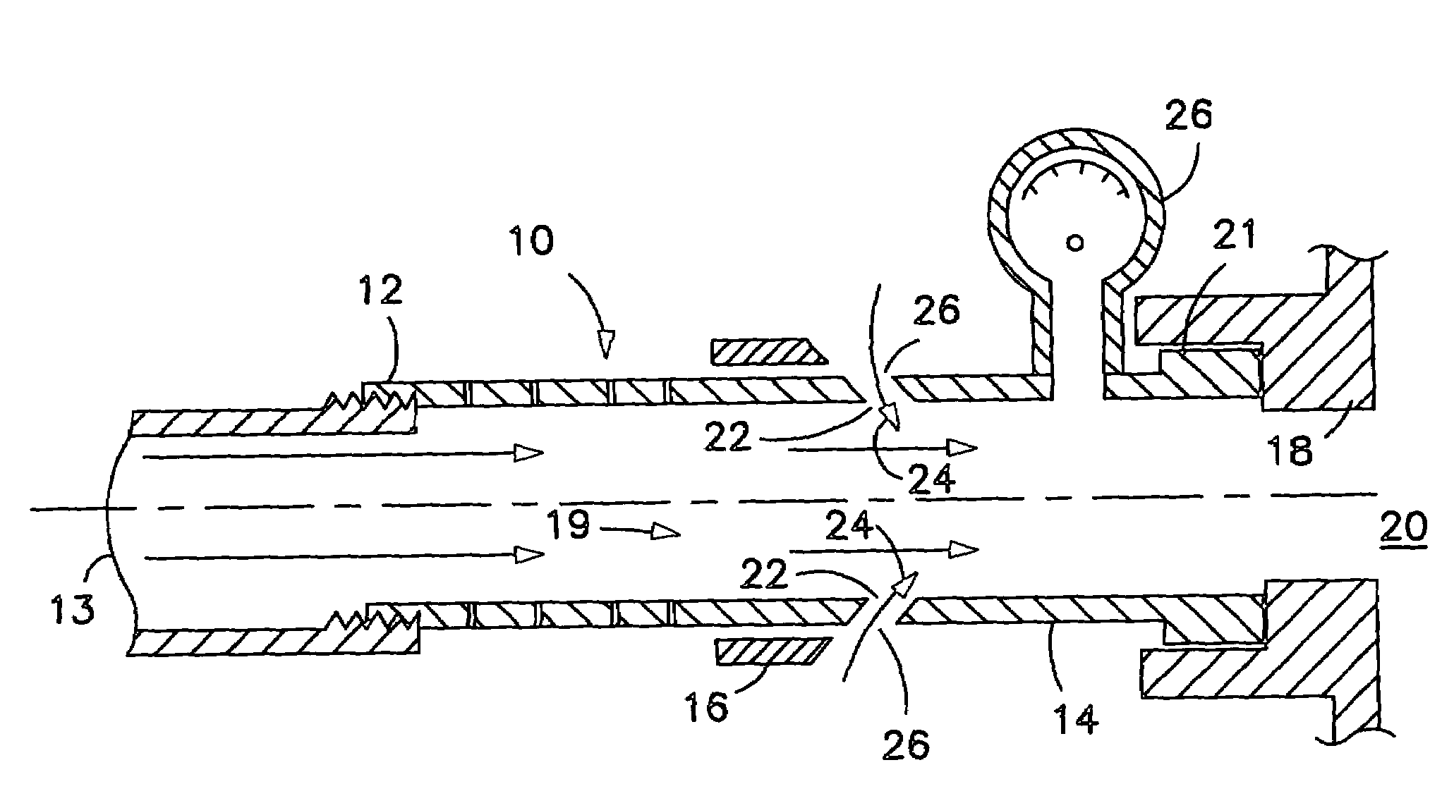
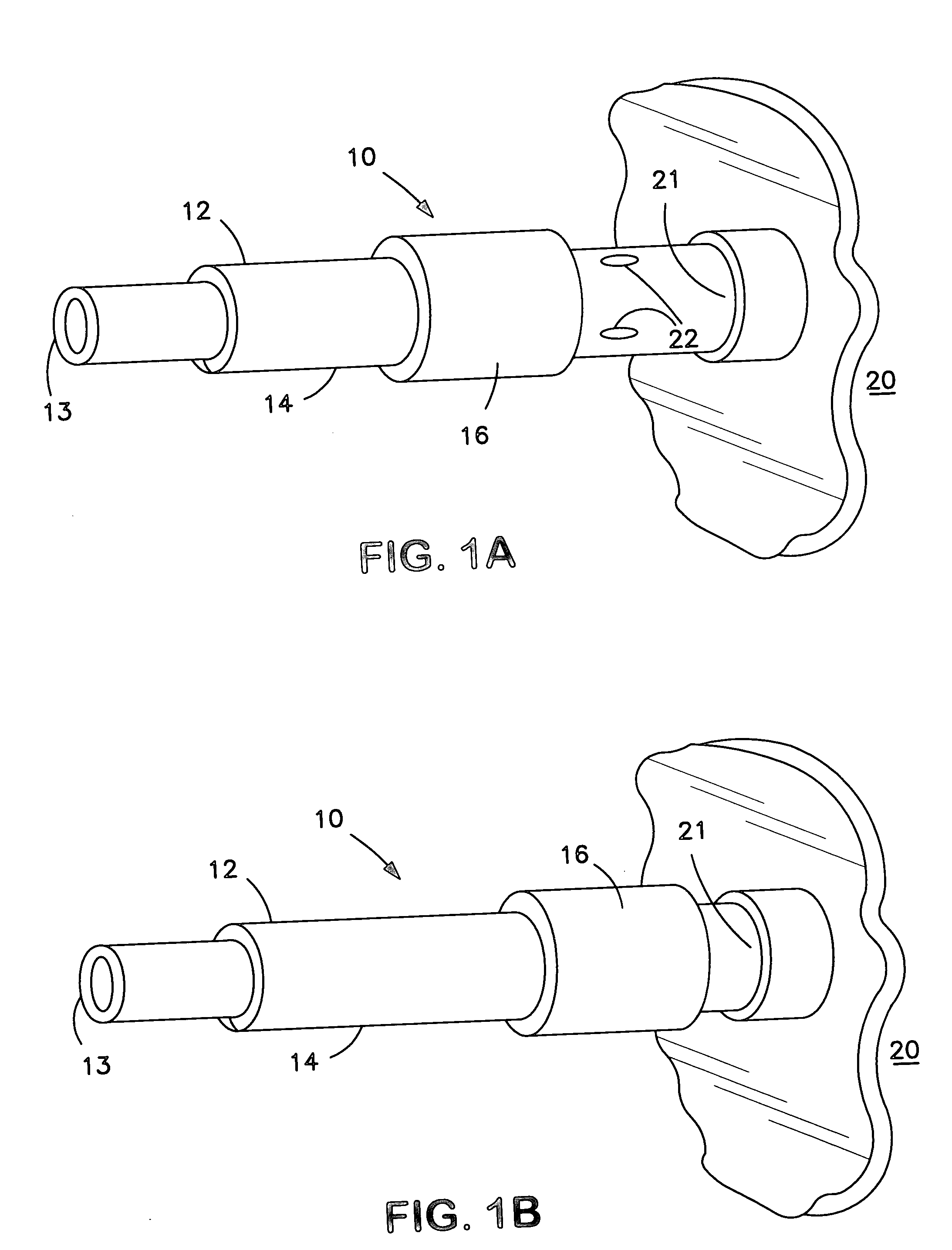
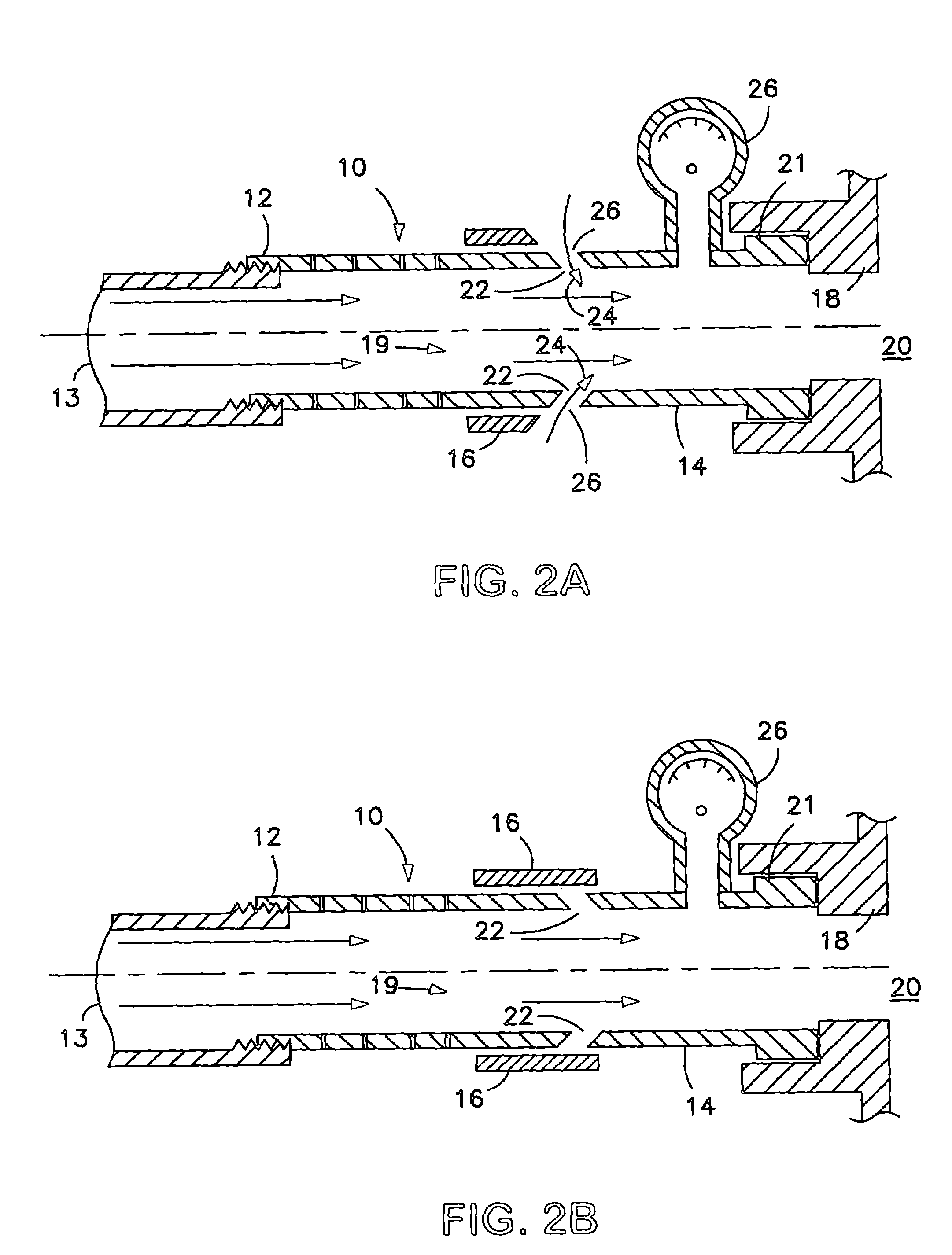
[0035]Turning now to a description of a best mode, FIGS. 1A, B are assembly views of one embodiment of the invention and FIGS. 2A, B are sectional views of FIGS. 1A, B respectively.

[0036]There is shown a nozzle 10 connected at a threaded entry end 12 to a source 13 of pressurized air. The exit end 21 of the nozzle is shown inserted into an entrance 21 of an air bag 20.

[0037]The nozzle 10 comprises a barrel section 14 and a sleeve 16 that slides telescopingly onto the barrel 14.

[0038]A plurality of venturi openings 22 is provided in the side of the barrel 14. Each venturi opening 22 is a tunnel 22 from the interior surface of the barrel 14 to the outside surface of the barrel 14. Each tunnel 22 slants from the opening in the interior surface of the barrel 14 backward to the outside opening of the tunnel 22 toward the entrance end 12 of the barrel 14.

[0039]FIG. 2A shows one position of the sleeve 16 on the barrel 14 where the sleeve 16 does not cover the tunnels 22, as air 19 flows th...


PUM

PropertyMeasurementUnit
Pressureaaaaaaaaaa
Flow rateaaaaaaaaaa
Sizeaaaaaaaaaa

Abstract

A nozzle for accelerating filling a container with gas up to a required gas pressure including a barrel having venturi openings in a side of said barrel and a sleeve that, in one position uncovers the tunnels and in another position, closes off the openings. In another version the nozzle further includes a pressure chamber, having a wall coupled to the sleeve. In a contracted position the sleeve is moved by the wall of the chamber to close off the tunnels. In another position of the wall where the chamber is in an expanded position the tunnels are so as to increase the rate of flow.

Description


Claims


Application Information

Patent Timeline
Owner SIGNODE IND GRP
Why Eureka
Try Eureka