Carrier for a bundle of fan folded sheet material to be converted into dunnage

a dunnage and carrier technology, applied in the direction of flexible container, stacking container, paper/cardboard article, etc., can solve the problems of severe jamming and the failure of the splicing adhesive to hold any pages together, and achieve the effect of preventing inwardly folded corners, high density and low density

Active Publication Date: 2015-01-15
RANPAK CORP
View PDF4 Cites 34 Cited by
  • Summary
  • Abstract
  • Description
  • Claims
  • Application Information

AI Technical Summary

Benefits of technology

[0005]The present invention adds removable, protective extensions to a carrier for stacks of fan-folded sheet material, preferably paper, that will be spliced to another stack before conversion to a dunnage product. The conversion process lowers the density, from a relatively high density of the sheet material to a relatively lower density of the resulting dunnage product. In previous carrier designs, a bottom layer of the stack can be inwardly folded under the stack during transport. If not noticed before attempting to splice the stack to another stack, more than two pages are secured together and are pulled as a unit into the dunnage conversion machine, often resulting in a severe jam. Other problems also can arise, such as a failure of the splicing adhesive to hold any pages together. The new protective extensions provided by the invention are left on the carrier during transport to protect the edges of the stack and prevent inwardly-folded corners of the pages. The protective extensions are removed by the operator to allow for secure splicing between two stacks without securing more than two pages together.

Problems solved by technology

If not noticed before attempting to splice the stack to another stack, more than two pages are secured together and are pulled as a unit into the dunnage conversion machine, often resulting in a severe jam.
Other problems also can arise, such as a failure of the splicing adhesive to hold any pages together.

Method used


Image

  • Carrier for a bundle of fan folded sheet material to be converted into dunnage
  • Carrier for a bundle of fan folded sheet material to be converted into dunnage
  • Carrier for a bundle of fan folded sheet material to be converted into dunnage

Examples


Embodiment Construction

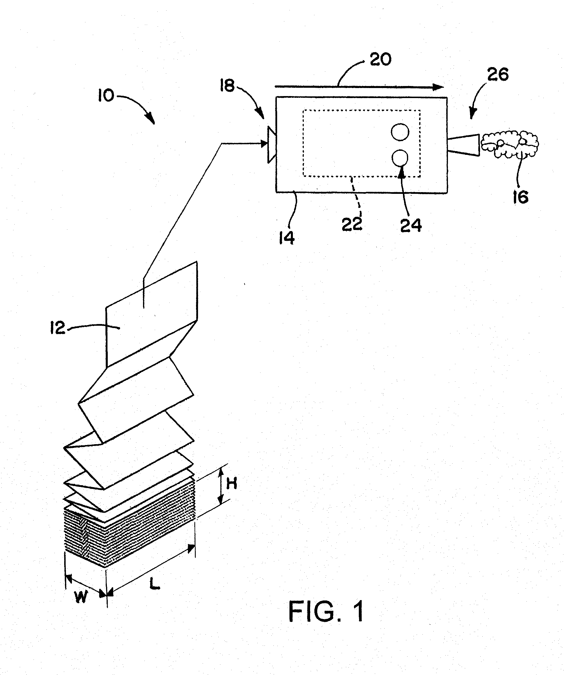
[0022]Referring now to the drawings in detail and initially to FIG. 1, there is shown a dunnage conversion system 10, including a stack of fan-folded sheet stock material 12 and a dunnage conversion machine 14. A series of folds together form a sequence of rectangular pages which are piled accordion style one on top of the other to form the stack of sheet stock material 12. The stack of fan-folded sheet material 12 has a height H, a width W, and a length L parallel to the folds that define the pages. The dunnage conversion machine 14 converts the sheet stock material 12, such as recyclable and reusable kraft paper, into a strip of relatively lower density dunnage product 16 including, for example, a relatively narrow three dimensional strip or rope of a generally cylindrical shape. The stock material 12 enters an upstream end 18 of the machine 14 and moves in an upstream-to-downstream direction 20 through a conversion assembly 22. The conversion assembly 22 typically includes one or...


PUM

PropertyMeasurementUnit
heightaaaaaaaaaa
widthaaaaaaaaaa
lengthaaaaaaaaaa

Abstract

A method of loading a stack of sheet stock material for use by a dunnage conversion machine, includes the following steps: (i) providing first and second stacks, the second stack being protected by a carrier having a central portion and longitudinally-spaced extensions that bound a central portion, the extensions and the central portion being joined along a weakened area defining a tear line, the central portion and the longitudinally-spaced extensions forming a planar bottom panel and a planar side panel, each panel extending substantially the length of the stack, and at a right angle to each other about a fold line over a bottom and an adjacent side of the stack, and one or more bale ties longitudinally inwardly of the tear lines holding the carrier to the stack; (ii) removing the extensions from the carrier; (iii) setting the second stack on top of the first stack; and (iv) removing the bale ties and the carrier, whereby an adhesive bonds the top page of the first stack to the bottom page of the second stack.

Description

RELATED APPLICATIONS [0001]This application claims the benefit of U.S. Provisional Patent Application No. 61 / 442,779, filed Feb. 14, 2011; U.S. patent application Ser. No. 13 / 117,585, filed May 27, 2011; which is a divisional of U.S. patent application Ser. No. 12 / 603,756, filed Oct. 22, 2009; which is a divisional of U.S. patent application Ser. No. 11 / 557,446, filed Nov. 7, 2006; which is a continuation of U.S. Pat. No. 11 / 184,354, filed Jul. 19, 2005; which is a divisional of U.S. patent application Ser. No. 10 / 420,519 filed Apr. 22, 2003, now U.S. Pat. No. 6,918,489; which claims the benefit under 35 USC §119(e) of earlier-filed U.S. Provisional Application Nos. 60 / 433,548, filed on Dec. 13, 2002; 60 / 421,996, filed on Oct. 29, 2002; 60 / 412,127, filed on Sep. 18, 2002; and 60 / 375,149, filed on Apr. 22, 2002; and all of these documents are hereby incorporated herein by reference in their entireties.FIELD OF THE INVENTION[0002]The present invention relates to the production of a du...

Claims


Application Information

Patent Timeline
Patent Type & Authority Applications(United States)
IPC IPC(8): B65D85/16B65G57/03B65D85/07
CPCB65D85/16B65G57/03B31D2205/0035B65D85/62B65H2701/1824B65H2701/1944B65H2801/63B65D85/07B65D75/5827B65D71/02B65D83/08B65D83/0805B65D5/54
Inventor YAP, FRANKLIN B.TONEFF, STEVEN M.CHEICH, ROBERT C.HARDING, JOSEPH J.SKIBA, JUDITH L.SIMMONS, JR., JAMES A.TEKAVEC, JAMESLINTALA, EDWARD W.METHORST, ERWINKUYPERS, KOEN H.M.COPPUS, DANDEMERS, RAIMOND P.M.KOBBEN, PIERRE
Owner RANPAK CORP
Why Eureka
Try Eureka