Solar powered fan for portable enclosure

a portable enclosure and solar energy technology, applied in lighting and heating apparatus, ventilation systems, heating types, etc., can solve the problems of negative effects on waste products and volatile compounds stored in enclosures, user control of air flow direction,

Inactive Publication Date: 2008-11-25
BARRETT RONALD GENE
View PDF28 Cites 22 Cited by
  • Summary
  • Abstract
  • Description
  • Claims
  • Application Information

AI Technical Summary

Benefits of technology

[0008]The solar powered fan for a portable enclosure includes an electrical fan, which is pivotally mounted within the interior region of a portable housing, such as that associated with a portable toilet facility. The pivotal mounting of the fan allows for selective user adjustment of the angular position of the fan with respect to the roof of the housing. The fan is mounted to a support arm, which is pivotally joined to a vertical support member. The vertical support member is rotatable about the vertical axis, providing user-selectable positioning of the fan about two axes of rotation.
[0010]Further, an adjustable collar is mounted on the vertical support member, within the interior of the enclosure. The collar threadedly engages the vertical support member and may be vertically adjusted to contact the roof of the enclosure, thus stabilizing the solar powered fan with respect to the enclosure's roof.

Problems solved by technology

The interiors of these enclosures can become quite warm in this sort of environment, which can have negative effects on waste products and volatile compounds stored within the enclosures, particularly in the generation of noxious and offensive fumes.
The user, however, does not have control over the direction of the air flow, since the fan is typically stably mounted on the roof of the structure, and the user is not provided with direct access to the fan.

Method used


Image

  • Solar powered fan for portable enclosure
  • Solar powered fan for portable enclosure
  • Solar powered fan for portable enclosure

Examples


Embodiment Construction

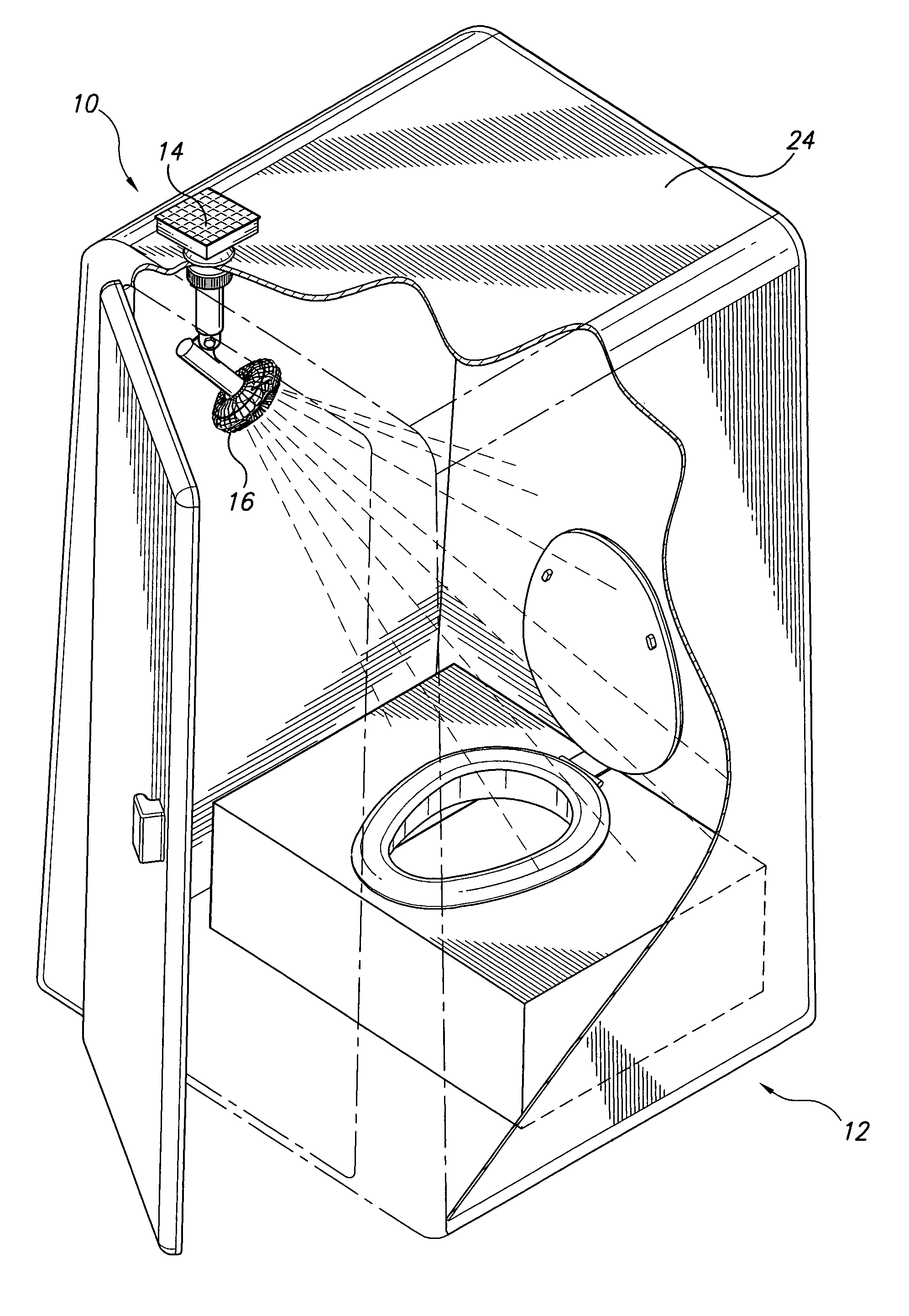
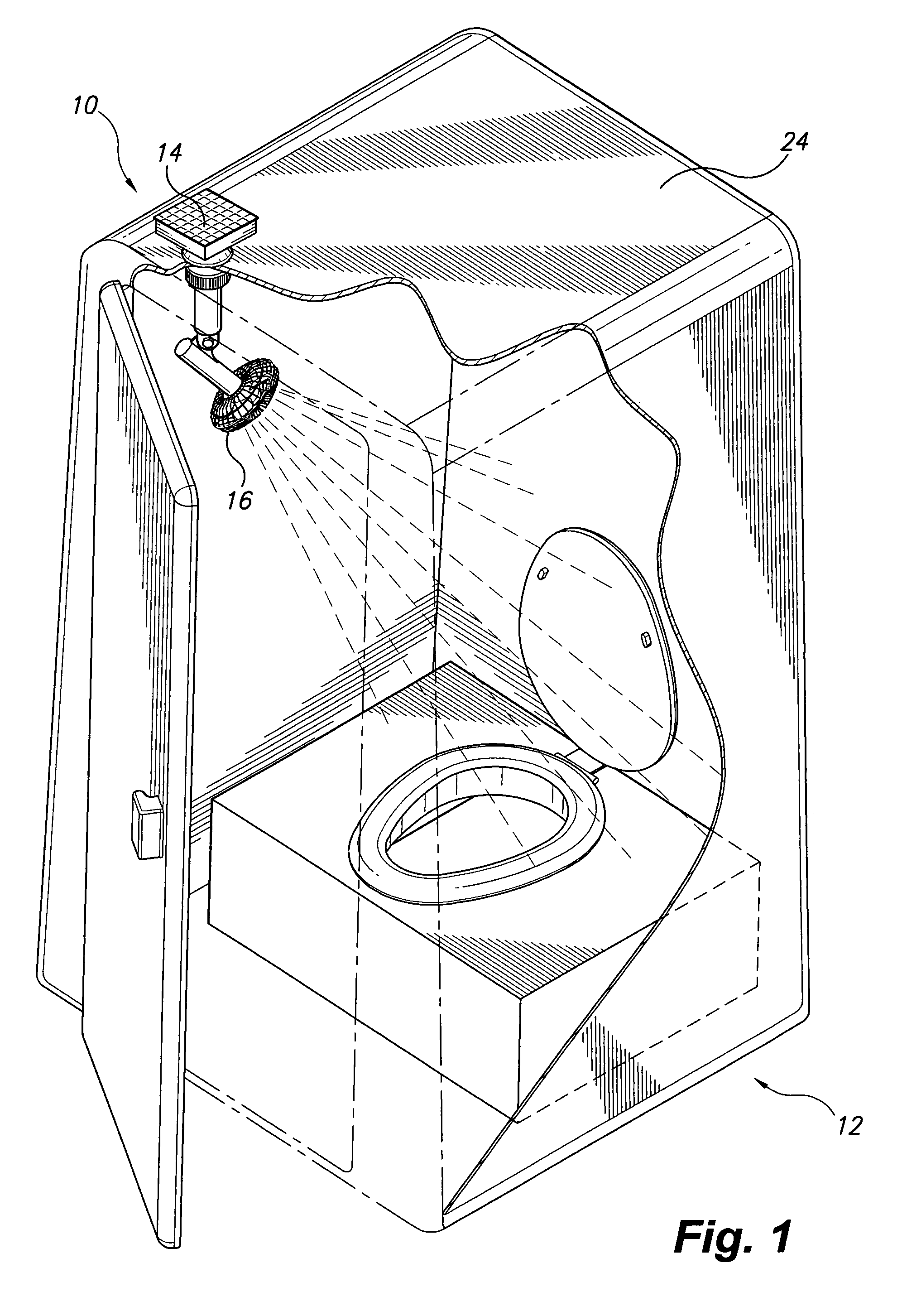
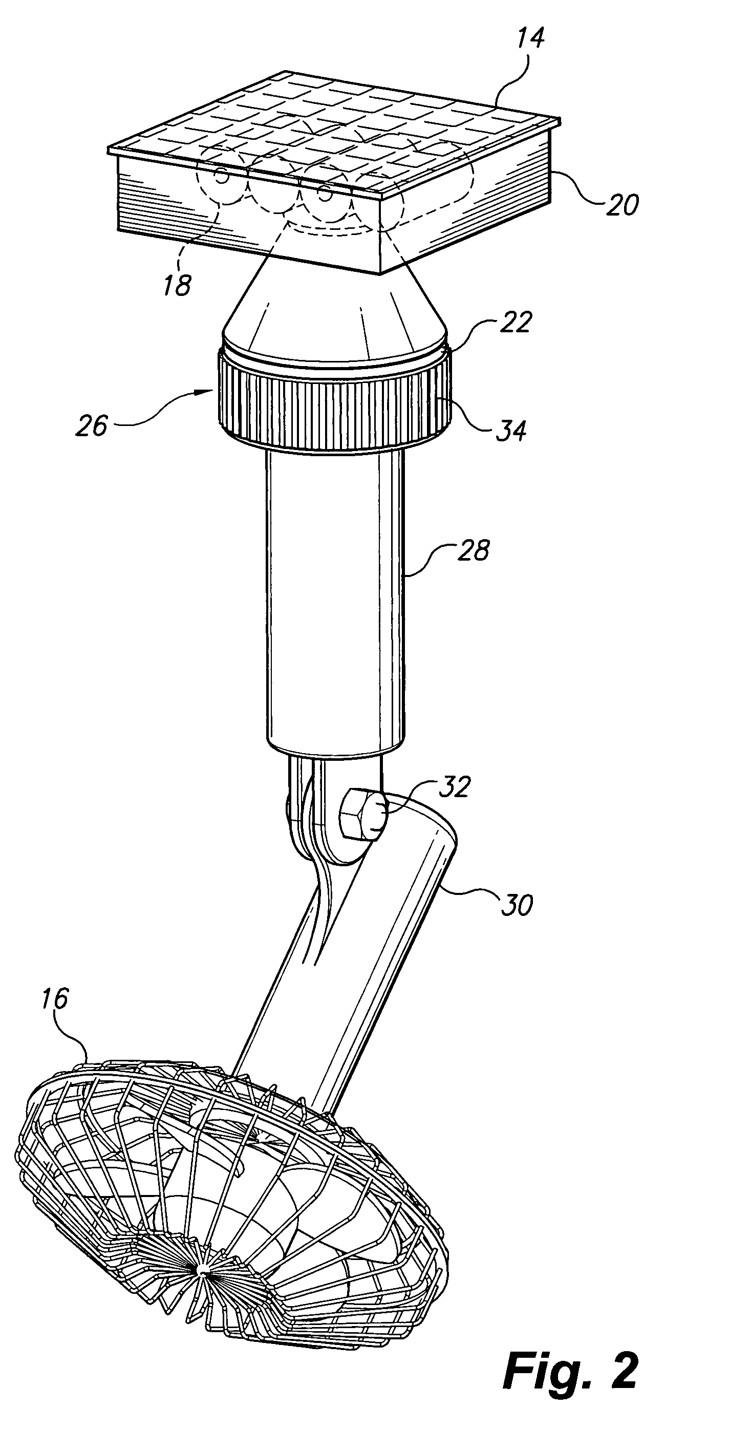
[0018]FIG. 1 illustrates the subject solar powered fan for a portable enclosure 10 mounted on the roof 24 of a portable shed 12, such as, for example, that associated with portable toilet facilities. As shown, system 10 includes an upper housing which is positioned on roof 24 and projects upwardly therefrom. At least one solar panel 14 is mounted on the upper housing for powering system 10, as will be further described below. Additionally, a fan 16 is pivotally mounted within the interior of enclosure 12, thus providing adjustable air flow within the enclosure 12 for the user. Power for fan 16 is provided by solar panel 14, which is positioned to receive direct sunlight, thus allowing system 10 to be mounted on any suitable enclosure 12, without the necessity of an exterior power source. It should be understood that the portable toilet facility 12 is shown for exemplary purposes only, and that system 10 may be utilized with any desired suitable portable enclosure.

[0019]As best shown...


PUM


Abstract

The solar powered fan for a portable enclosure includes an electrical fan, which is pivotally mounted within the interior region of a portable edifice, such as that associated with a portable toilet facility. The pivotal mounting of the fan allows for selective user adjustment of the angular position of the fan with respect to the roof of the housing. Mounted on the roof, exterior to the enclosure, is a hollow housing having at least one solar panel mounted to an upper surface thereof. The solar panel charges a rechargeable battery received within the hollow housing which, in turn, is in electrical communication with the electrical fan.

Description

CROSS-REFERENCE TO RELATED APPLICATION[0001]This application claims the benefit of U.S. Provisional Patent Application Ser. No. 60 / 740,627, filed Nov. 30, 2005.BACKGROUND OF THE INVENTION[0002]1. Field of the Invention[0003]The present invention relates to a solar powered fan for a portable enclosure, which includes an electrical fan pivotally mounted within the interior region of a portable edifice, such as that associated with a portable toilet facility. Particularly, the system includes a solar panel mounted on the roof of the enclosure, which charges a rechargeable battery in electrical communication with the electrical fan.[0004]2. Description of the Related Art[0005]Portable enclosures, such as tool sheds and, in particular, portable toilet facilities, are often positioned in environments where they are exposed to direct sunlight, such as construction sites and the like. The interiors of these enclosures can become quite warm in this sort of environment, which can have negativ...

Claims


Application Information

Patent Timeline
Patent Type & Authority Patents(United States)
IPC IPC(8): F24F7/007E04H15/14
CPCE04H1/1216F04D15/0218F24F7/007F04D13/086Y02B10/24Y10S454/90F24F2005/0064Y02B10/20Y02A30/272
Inventor BARRETT, CORY G.
Owner BARRETT RONALD GENE
Why Eureka
Try Eureka