Support installation for a fairground attraction

a technology for supporting installations and fairgrounds, which is applied in the direction of great wheels, russian swings, amusements, etc., can solve the problems of restricted height of support installations and high undesirable heights in the erected position, and achieve the effect of increasing the height of support installations and increasing attractions

Active Publication Date: 2008-11-25
COBRA BEHEER
View PDF8 Cites 1 Cited by
  • Summary
  • Abstract
  • Description
  • Claims
  • Application Information

AI Technical Summary

Benefits of technology

[0005]The aim of the present invention is to provide a support installation for a fairground attraction that can be collapsed and does not have this disadvantage, so that higher attractions are possible. Said aim is achieved in that each mast has a base segment that is joined to the base such that it can pivot, as well as a top segment that is joined to the head, at least in the erected position. Because both base segments are joined to the base such that they can pivot, the height of the support installation can be appreciably increased. For example, both the base segment and the top segment can be approximately the same length as the base, without protruding with respect to said base in the collapsed position. By this means the height of the support installation can therefore be approximately twice that of the known support installation.

Problems solved by technology

This is highly undesirable, especially also because of the fact that the base is usually constructed as a trailer for transport by road.
One disadvantage of this support installation is, therefore, that the height thereof is restricted in the erected position.

Method used


Image

  • Support installation for a fairground attraction
  • Support installation for a fairground attraction
  • Support installation for a fairground attraction

Examples


first embodiment

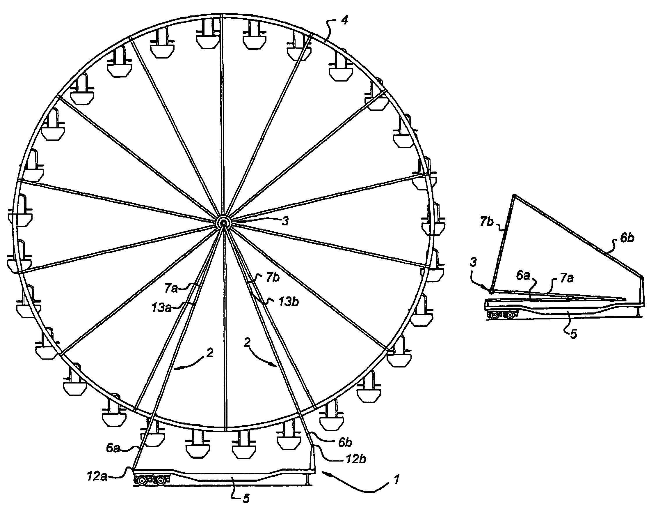
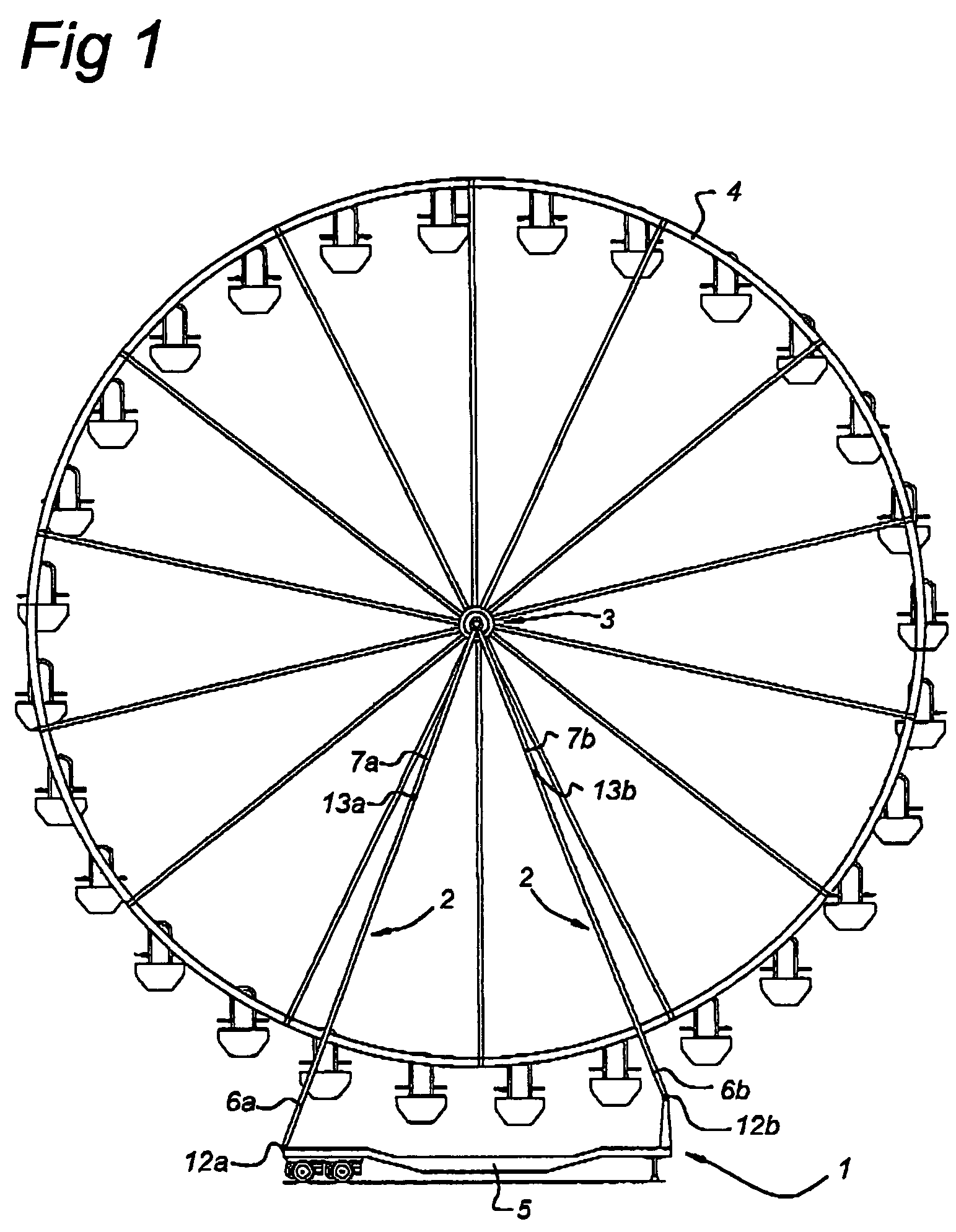
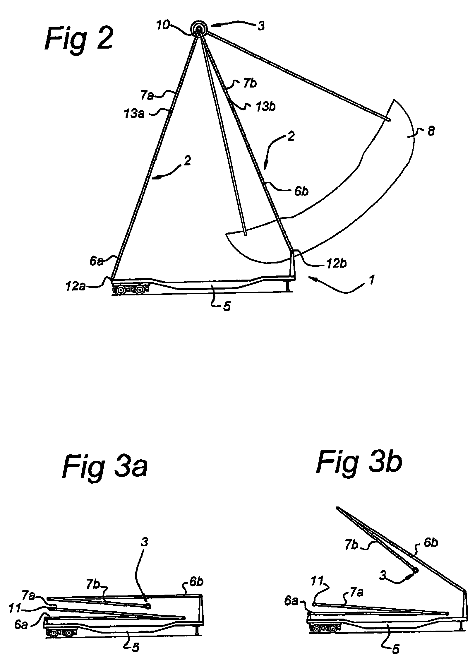
[0020]FIG. 3 shows the erection of a pair of masts according to the invention. Each mast has a base segment 6a, 6b and a top segment 7a, 7b, which are essentially the same length as the base. In the collapsed position these segments are alongside one another and along the base, as shown in FIG. 3a. When erecting the support installation, the base segment 6b of one of the pair of masts is first raised, see FIG. 3b, until the top segment 7b of said mast can be coupled by means of a detachable coupling 11 to the top segment 7a of the other mast, see FIG. 3c. The support installation can then be fully erected by raising the base segments 6a, 6b, as can be seen in FIGS. 3d to 3h, the top segments remaining coupled such that they can pivot.

second embodiment

[0021]FIG. 4 shows the erection of a pair of masts according to the invention. Each mast has a base segment 6a, 6b that is essentially the same length as the base 5, and a top segment 7a, 7b, the length of which is approximately equal to half that of the base segment. The top segments are joined to one another by means of a permanent pivot coupling 10. In the collapsed position the segments are alongside one another and along the base, as shown in FIG. 4a. The support installation can now be erected by raising the base segments, as shown in FIGS. 4b to 4h.

[0022]The support installations in FIG. 4 and FIG. 3 can be stabilised by fixing the base segments with respect to the base; the top segments then have no further freedom of movement. FIG. 5 shows one possible embodiment of such stabilisation, where fixing is effected by means of actuators 9 which also provide for erection of the support installation. These actuators can, for example, be constructed as hydraulic piston / cylinder de...


PUM


Abstract

A support installation for a fairground attraction, comprises a base, two pairs of masts which can be moved between a collapsed and an erected position, as well as a head that in the erected position is at the top of the masts, on which head a Ferris wheel or a swing or the like can be mounted, wherein the masts each comprise several segments that are joined to one another such that they can pivot. Each mast has a base segment that is joined to the base such that it can pivot, as well as a top segment that is joined to the head, at least in the erected position. Relatively high masts can be obtained with this construction.

Description

BACKGROUND OF THE INVENTION[0001]1. Field of the Invention[0002]The invention relates to a support installation for a fairground attraction, comprising a base, two pairs of masts which can be moved between a collapsed and an erected position, as well as a head, which is at the top of the masts when the masts are in the erected position, for fixing a Ferris wheel or a swing or the like thereto, wherein the masts each comprise several segments that are joined to one another such that they can pivot.[0003]2. Description of the Related Art[0004]A support installation of this type is disclosed in U.S. Pat. No. 6,634,952 B2. With this installation the masts of each pair in the erected position form two sides of a triangle and the base forms the third side of said triangle. The base segment of one of the masts of each pair is fixed with respect to the base, whilst the base segment of the other mast is joined to the base such that it can pivot. Said fixed base segment is relatively short, s...

Claims


Application Information

Patent Timeline
Patent Type & Authority Patents(United States)
IPC IPC(8): A63G1/28
CPCA63G1/00A63G9/00A63G27/00A63G2200/00
Inventor KROON, ALBERT LOUISITO PHILLIPUS
Owner COBRA BEHEER
Why Eureka
Try Eureka