Control system for bearingless motor-generator

Inactive Publication Date: 2008-11-25
UNIVERSITY OF TOLEDO
View PDF29 Cites 27 Cited by
  • Summary
  • Abstract
  • Description
  • Claims
  • Application Information

AI Technical Summary

Benefits of technology

[0008]The present invention is directed toward a control system for an electromagnetic rotary drive for bearingless motor-generators that meets the foregoing needs. The control system comprises a winding configuration comprising a plurality of individual pole pairs through which phase currents flow, each phase current producing both a lateral force and a torque.
[0009]The present invention is also directed toward a bearingless motor-generator. The motor-generator comprises a stator, a rotor supported for movement relative to the stator, and a control system. The motor-generator comprises a winding configuration supported by the stator. The winding configuration comprises at least three pole pairs through which phase currents flow resulting in three three-phase systems. Each phase system has a first rotor reference frame axis current that produces a levitating force with no average torque and a second rotor reference frame axis current that produces torque.

Problems solved by technology

However, this control system produces no forces for levitating the rotating part, since poles carry the same flux, and balance their forces out.

Method used


Image

  • Control system for bearingless motor-generator
  • Control system for bearingless motor-generator
  • Control system for bearingless motor-generator

Examples


Embodiment Construction

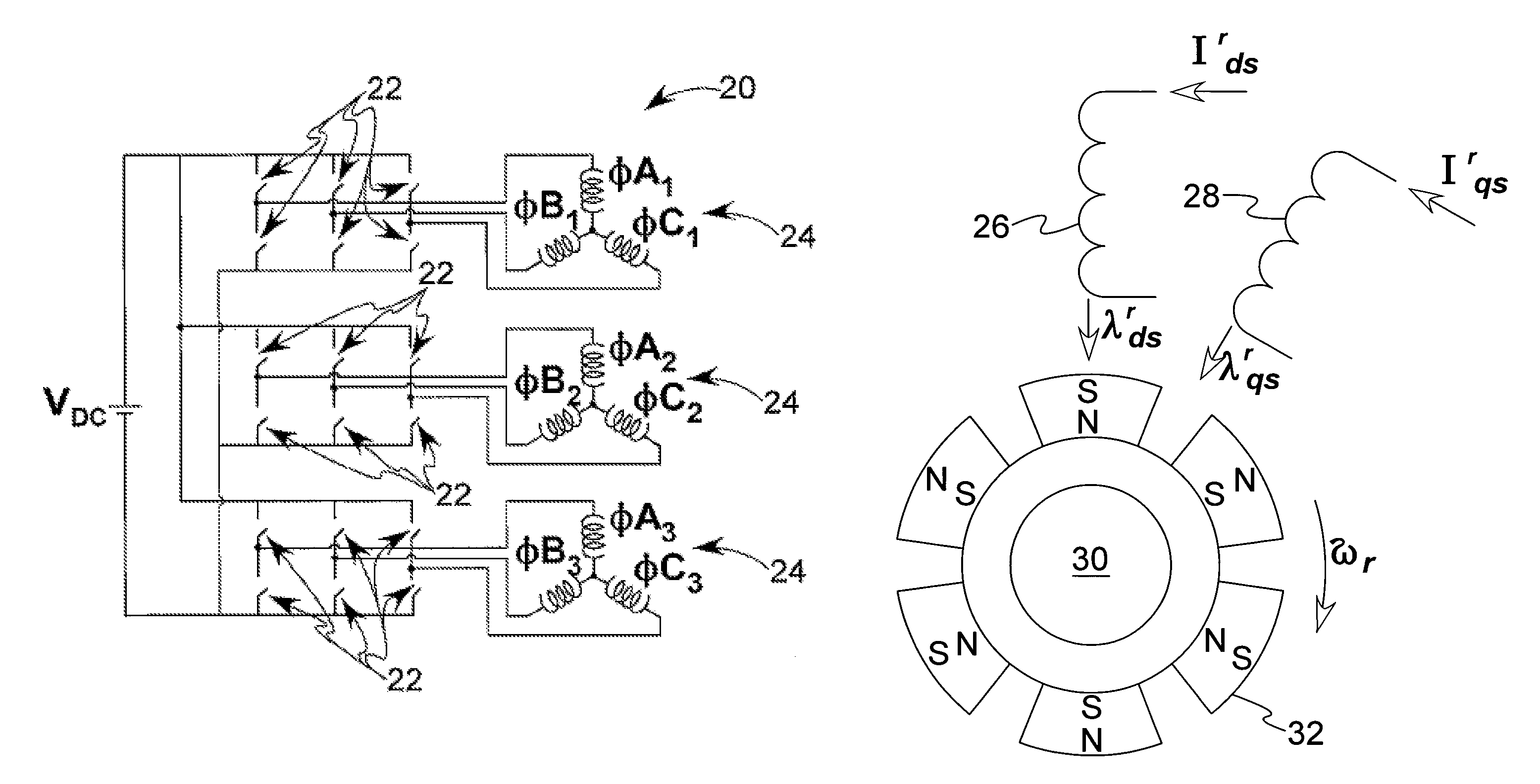
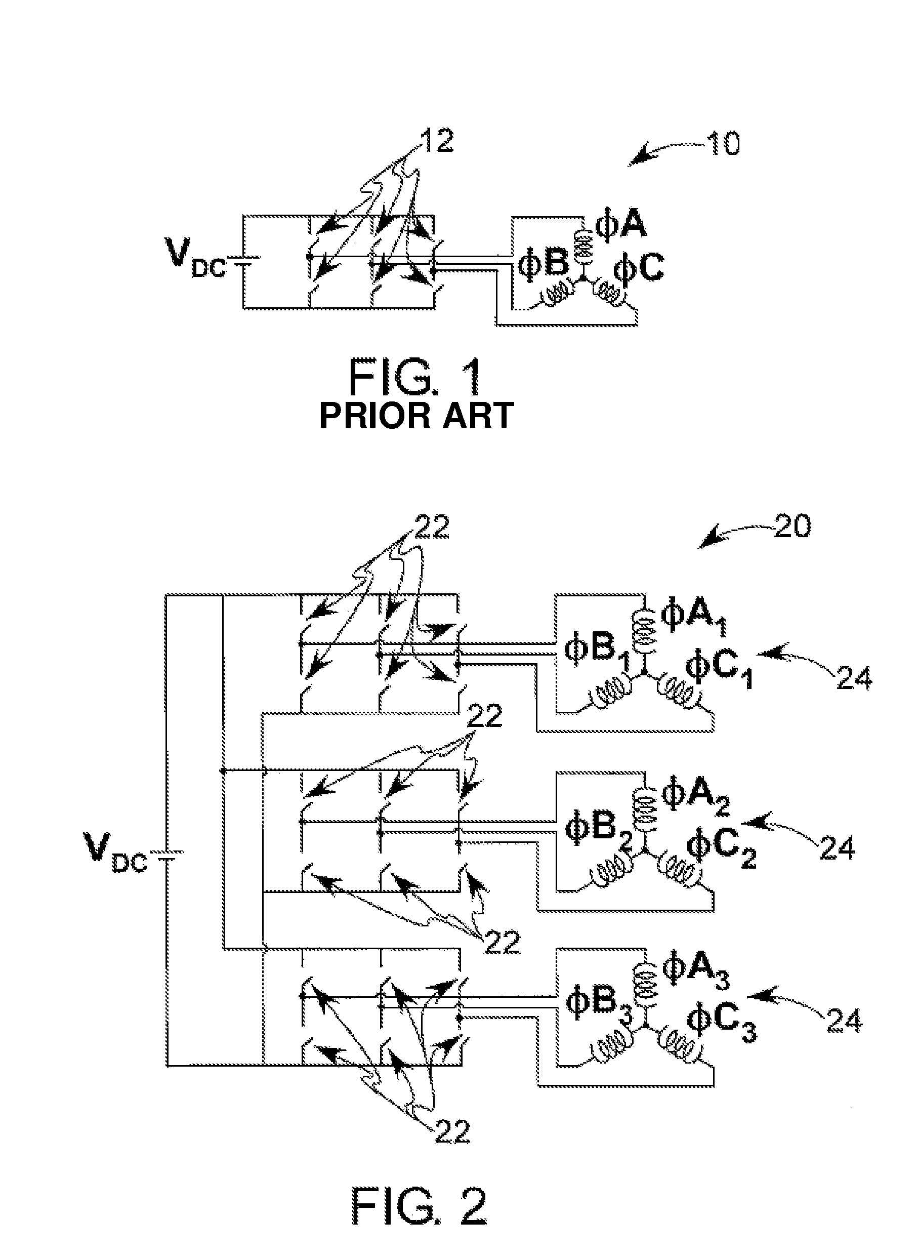
[0036]Referring now to the drawings, there is illustrated in FIG. 2 a cylindrical motor control system 20 for an electromagnetic rotary drive for use in a cylindrical bearingless motor-generator (hereinafter “motor”). It should be noted that the standard motor drive control system described above has only six switches 12, while the control system 20 shown in FIG. 2 has eighteen switches 22. As a consequence, the control system 20 can stimulate three systems of three phases. Each of these systems comprises a pole pair system, generally indicated at 24, resulting in three pole pair systems. Although there are three times as many switches, the required power rating for each switch 22 is much smaller than that for the conventional control system 10 described above. For example, if the number of turns in the motor is kept constant, the voltage the switches 22 would be required to block would be one third of the normal system voltage of the conventional control system 10. If the motor is ...


PUM


Abstract

A control system for an electromagnetic rotary drive for bearingless motor-generators comprises a winding configuration comprising a plurality of individual pole pairs through which phase current flows, each phase current producing both a lateral force and a torque. A motor-generator comprises a stator, a rotor supported for movement relative to the stator, and a control system. The motor-generator comprises a winding configuration supported by the stator. The winding configuration comprises at least three pole pairs through which phase current flows resulting in three three-phase systems. Each phase system has a first rotor reference frame axis current that produces a levitating force with no average torque and a second rotor reference frame axis current that produces torque.

Description

CROSS REFERENCE TO RELATED APPLICATIONS[0001]This application is a continuation of U.S. Provisional Patent Application Ser. Nos. 60 / 637,280, which was filed on Dec. 17, 2004, and the description of which is incorporated herein by reference.[0002]This invention was made with government support under NCC3-916 and NCC3-924 awarded by NASA. The government has certain rights in the invention.BACKGROUND OF INVENTION[0003]The present invention generally relates to an electromagnetic rotary drive and more particularly, to an electromagnetic rotary drive that functions as a bearingless motor-generator. Most particularly, the invention relates to a control system for a bearingless motor-generator.[0004]Electromagnetic rotary drives are commonly used in standard motors as well as bearingless motor-generators. A conventional electromagnetic rotary drive includes a rotating part and a stationary part. The rotary part is commonly referred to as a rotor and the stationary part is commonly referred...

Claims


Application Information

Patent Timeline
Patent Type & Authority Patents(United States)
IPC IPC(8): H02K7/09H02P21/00H02P5/00
CPCF16C32/0446F16C32/0493H02K7/09H02P21/0003H02P25/16
Inventor KASCAK, PETER E.JANSEN, RALPH H.DEVER, TIMOTHY P.
Owner UNIVERSITY OF TOLEDO
Why Eureka
Try Eureka