System and method for compressing information in a communications environment

Active Publication Date: 2008-11-25
CISCO TECH INC
View PDF18 Cites 81 Cited by
  • Summary
  • Abstract
  • Description
  • Claims
  • Application Information

AI Technical Summary

Benefits of technology

[0005]Certain embodiments of the present invention may provide a number of technical advantages. For example, according to one embodiment of the present invention, a communications approach is provided that significantly enhances bandwidth parameters for a given architecture. This is a result of a compression technique that tracks the state of a time-division multiplexed (TDM) stream and represents the state of the A-bis voice or data call by a context. This context may be maintained for each sub-rate digital signaling zero (DS0) segment. The context may be efficiently translated into commands for a compressor and/or a decompressor.
[0006]Such an operation optimizes bandwidth allocations for a given architecture. For example, when the sub-rate DS0 channel is IDLE (e.g. alternating 01 pattern), in an ERROR state (e.g. all zeros), or when no call is assigned to the channel, there is zero bandwidth required to represent the contents of the channel. Thus, minimal bandwidth is consumed as a result of such an operation. Additionally, when the voice/data frame contains silence (or any other frame filler), no bandwidth is required to represent the silence or filler data. This further increases available bandwidth.
[0007]Another

Problems solved by technology

Many proposed solutions for effectuating proper data exchanges add significant overhead and cost in order to accommodate a large number of end users.
For example, a large number of T1/E1 lines may be implemented, but such lines are generally expensive and, thus, each one should be maximized in order to achieve optimal system performance.
Operations that achieve

Method used


Image

  • System and method for compressing information in a communications environment
  • System and method for compressing information in a communications environment
  • System and method for compressing information in a communications environment

Examples


Example

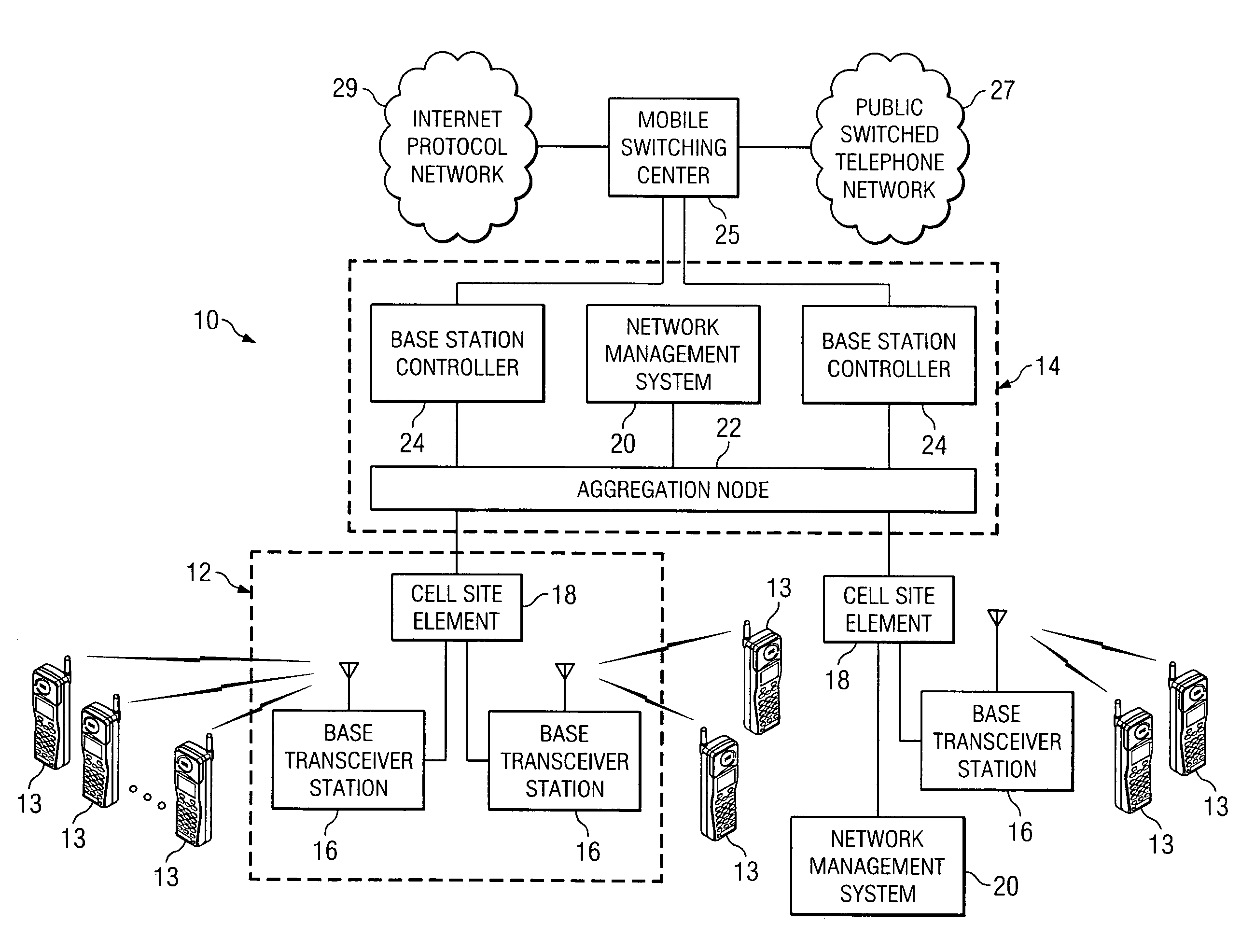
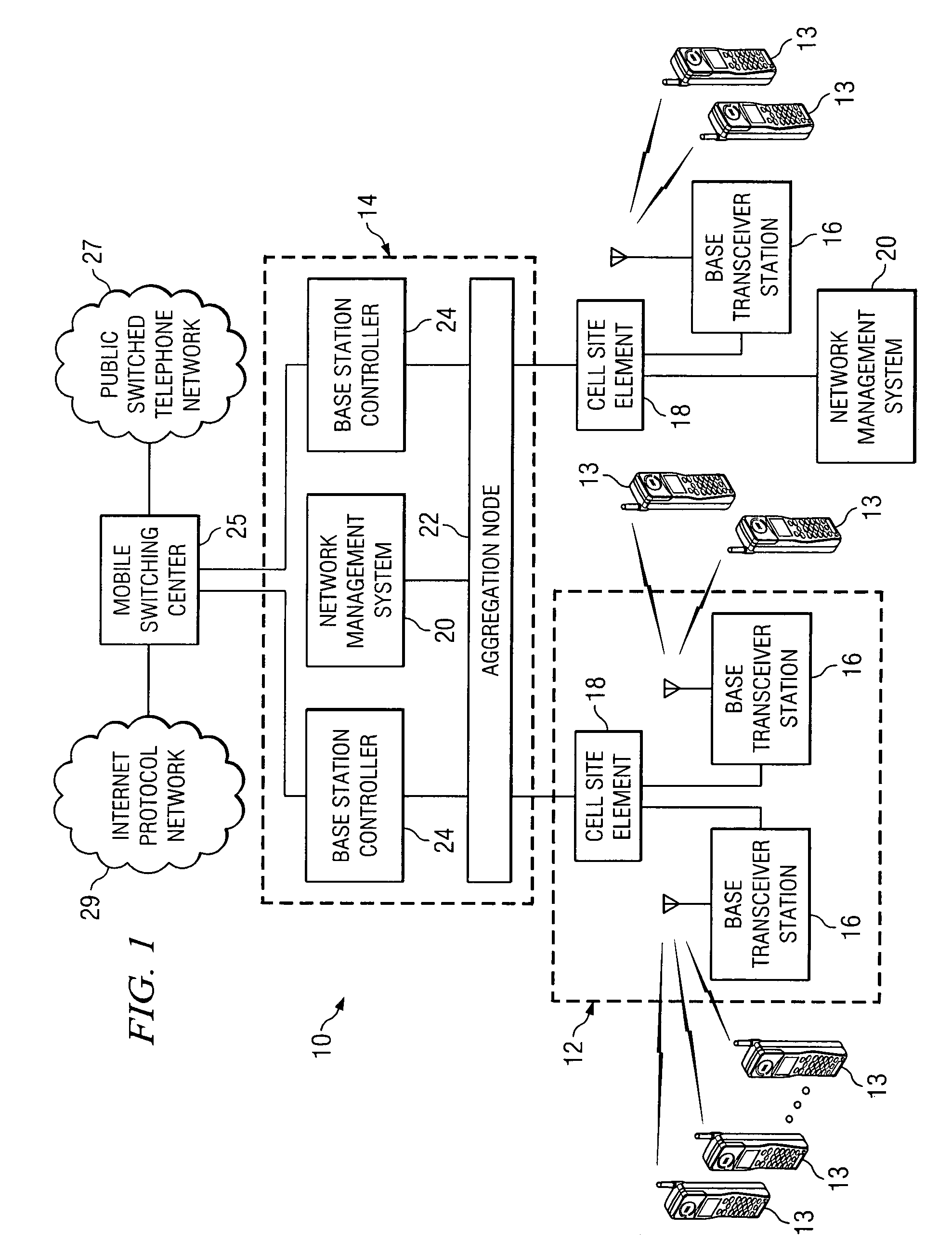
[0012]FIG. 1 is a simplified block diagram of a communication system 10 for compressing data in a communications environment. Communication system 10 may include a plurality of cell sites 12, a plurality of mobile stations 13, a central office site 14, a plurality of base transceiver stations 16, a plurality of cell site elements 18, and a network management system 20. Additionally, communication system 10 may include an aggregation node 22, a plurality of base station controllers 24, a mobile switching center 25, a public switched telephone network (PSTN) 27, and an internet protocol (IP) network 29.

[0013]Communication system 10 may generally be configured or arranged to represent a 2.5G architecture applicable to a Global System for Mobile (GSM) environment in accordance with a particular embodiment of the present invention. However, the 2.5G architecture is offered for purposes of example only and may alternatively be substituted with any suitable networking system or arrangement...


PUM


Abstract

A method for compressing information is provided that includes receiving a plurality of bits associated with a communications flow and tracking a state of a channel associated with the communications flow. A payload may be determined for a portion of the communications flow based on the state of the channel. The payload may then be communicated to a next destination.

Description

TECHNICAL FIELD OF THE INVENTION[0001]The present invention relates in general to the field of communications and, more particularly, to a system and a method for compressing information in a communications environment.BACKGROUND OF THE INVENTION[0002]Communication systems and architectures have become increasingly important in today's society. One aspect of communications relates to maximizing bandwidth and minimizing delays associated with data and information exchanges. In compression scenarios, network operators generally seek to produce high percentages of gain in compression for any given transport that is being implemented. Many proposed solutions for effectuating proper data exchanges add significant overhead and cost in order to accommodate a large number of end users. For example, a large number of T1 / E1 lines may be implemented, but such lines are generally expensive and, thus, each one should be maximized in order to achieve optimal system performance. A provider general...

Claims


Application Information

Patent Timeline
IPC IPC(8): H04J3/24
CPCG10L19/012
Inventor SMITH, MALCOLM M.
Owner CISCO TECH INC
Why Eureka
Try Eureka