
Automatic shutdown or throttling of a bist state machine using thermal feedback

a bist state machine and automatic shutdown technology, applied in measurement devices, error detection/correction, instruments, etc., can solve problems such as the risk of temperature limits being reached or exceeded, the gap between how a chip is being tested functionally and how it is being used, and the risk of temperature limits being particularly acute for embedded memories

Inactive Publication Date: 2008-11-25
INT BUSINESS MASCH CORP
View PDF6 Cites 20 Cited by
  • Summary
  • Abstract
  • Description
  • Claims
  • Application Information

AI Technical Summary

Benefits of technology

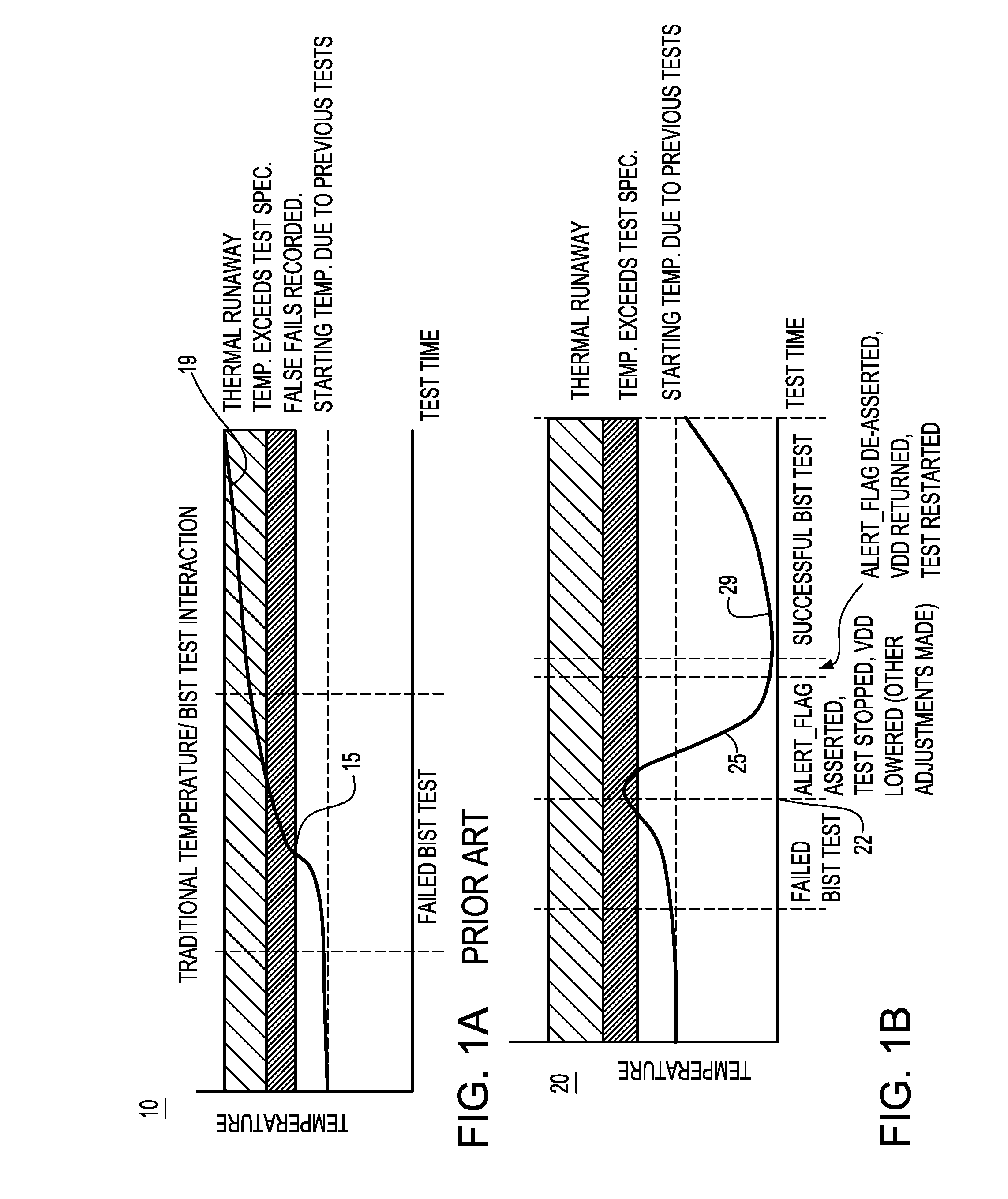
[0016]During a standby “idle” condition, dropping Vdd by a pre-specified amount will significantly reduce background leakage, allowing the temperature to be brought under control, without losing the valid BIST failing address data that has been collected up to this point. During the “idle” condition it may also be necessary to adjust the test conditions to help maintain temperature control upon resuming test, such as reducing the number of memories being tested, reducing the frequency of clocks during test or reducing the length of test.

Problems solved by technology

As such, there is an ever-increasing gap between how a chip is being used functionally and how it is being tested.
In today's BIST test approaches, the problem becomes particularly acute for embedded memories on a die that are all continually self-tested in parallel at elevated voltage and temperature conditions.
As such, embedded memory designs run the risk of temperature limits being reached or exceeded thus rendering such continuous and parallel self-testing of all memories on a die not possible.

Method used


Image

  • Automatic shutdown or throttling of a bist state machine using thermal feedback
  • Automatic shutdown or throttling of a bist state machine using thermal feedback
  • Automatic shutdown or throttling of a bist state machine using thermal feedback

Examples


first embodiment

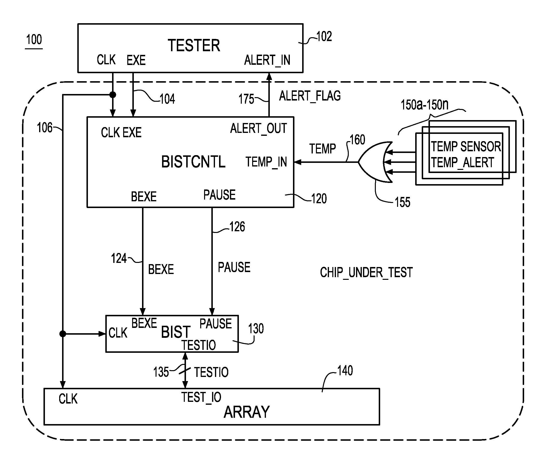
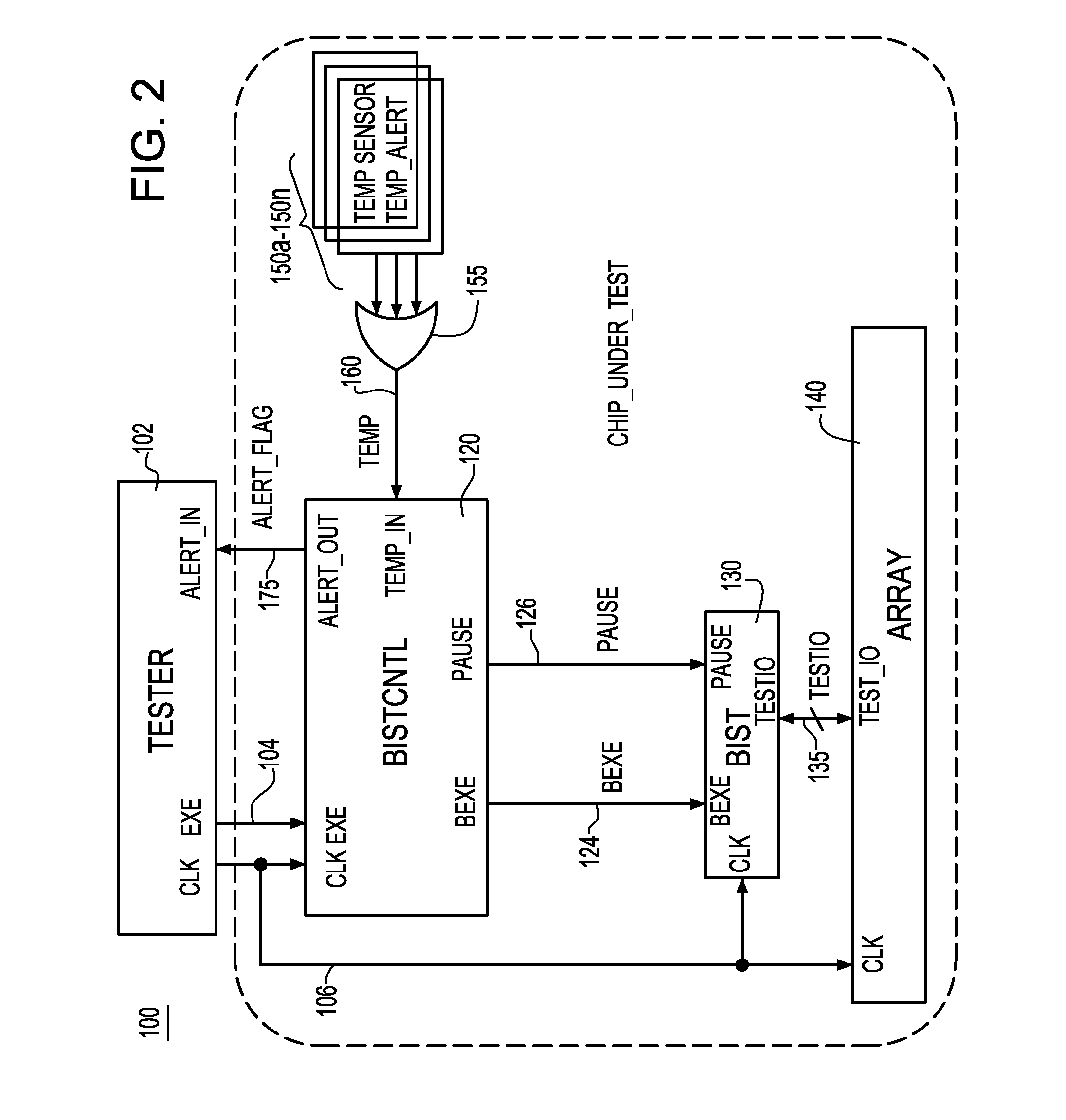
[0027]FIG. 3A depicts a BIST test methodology 200 according to the invention where test results of suspect circuits (e.g., memories) are ignored. As shown in FIG. 3A, the BIST test array executes at 205 until a TEMP signal 160 is asserted at 207 in response to the logic applied at the outputs of the one or more on-chip thermal sensor devices 150a, . . . , 150n. Upon receipt of the TEMP signal by BIST / CNTL circuit 120 (FIG. 2), the process proceeds to step 209 which represent the step of BIST / CNTL circuit 120 asserting the ALERT_FLAG 175 to the tester device and further asserting a PAUSE signal 126 to the BIST. In response to receipt of the PAUSE signal 126, BIST testing ceases collecting BIST test results as indicated at 212 until the BIST sub-pattern currently being executed completes as indicated at step 215. At such time, the BIST suspends all operations as indicated at step 219 and the tester device 102 lowers the chip under test's operating power source voltage VDD as indicated...

second embodiment

[0030]FIG. 4A depicts a BIST test methodology 300 according to the invention wherein the testing of suspect circuits (e.g., suspect memories) is temporarily stopped. As shown in FIG. 4A, the BIST test array executes at 305 until a TEMP signal 160 is asserted at 307 in response to the logic applied at the outputs of the one or more on-chip thermal sensor devices 150a, . . . , 150n. Upon receipt of the TEMP signal by BIST / CNTL circuit 120 (FIG. 2), the process proceeds to step 309 which represent the step of BIST / CNTL circuit 120 asserting the ALERT_FLAG 175 to the tester device and further asserting a PAUSE signal 126 to the BIST. In response to receipt of the PAUSE signal 126, the BIST stops testing the array as indicated at step 312 and returns to the sub-pattern at the initial (start) state at 315. After returning to the sub-pattern at the initial (start) state at 315, the BIST suspends all operations as indicated at step 319 and the tester device 102 lowers the chip under test's ...


PUM


Abstract

A Built-In-Self-Test (BIST) state machine providing BIST testing operations associated with a thermal sensor device(s) located in proximity to the circuit(s) to which BIST testing operations are applied. The thermal sensor device compares the current temperature value sensed to a predetermined temperature threshold and determines whether the predetermined threshold is exceeded. A BIST control element suspends the BIST testing operation in response to meeting or exceeding said predetermined temperature threshold, and initiates resumption of BIST testing operations when the current temperature value normalizes or is reduced. A BIST testing methodology implements steps for mitigating the exceeded temperature threshold condition in response to determining that the predetermined temperature threshold is met or exceeded. These steps include one of: ignoring the BIST results of the suspect circuit(s), or by causing the BIST state machine to enter a wait state and adjusting operating parameters of the suspect circuits while in the wait state.

Description

FIELD OF THE INVENTION[0001]The present invention relates generally to built in self-test (BIST) systems for use in semiconductor devices, and more particularly, to a system and method for controlling execution of device BIST testing based on thermal feedback information from the chip.DESCRIPTION OF THE PRIOR ART[0002]Chip designers are starting to imbed thermal measurement devices in order to be able to control the functional behavior of the chip to avoid thermal runaway, to minimize power consumption, or to be able to keep a section of the chip operating within a certain temperature range.[0003]As chip designs become ever more complex, built-in-self-test (BIST) mechanisms become more prevalent. As such, there is an ever-increasing gap between how a chip is being used functionally and how it is being tested. It is quite conceivable that with disabled functional power-saving methods such as clock gating and voltage islands coupled with structured self-test methods deployed at other ...

Claims


Application Information

Patent Timeline
Patent Type & Authority Patents(United States)
IPC IPC(8): G01R31/28
CPCG11C29/16G11C2029/5002
Inventor GORMAN, KEVIN W.KELLER, EMORY D.OUELLETTE, MICHAEL R.
Owner INT BUSINESS MASCH CORP
Learn More