Taping knife with offset handle

a technology of offset handle and taping knife, which is applied in the field of hand tools and hand tool handles, can solve the problems of inability to properly grip the knife, difficulty or discomfort of users with smaller hands, and inability to maintain a firm grip on the knife and control, so as to reduce wrist stress and overall fatigue, and prevent the user's hand from slipping

Active Publication Date: 2008-12-02
UNITED STATES GYPSUM CO
View PDF21 Cites 19 Cited by
  • Summary
  • Abstract
  • Description
  • Claims
  • Application Information

AI Technical Summary

Benefits of technology

[0007]The present taping knife responds to the above identified needs felt by construction, home decorating, and home repair professionals, as well as do-it-yourself workers. The present taping knife has a handle with an angular, non-perpendicular orientation relative to the working edge of the taping knife blade. This angular offset allows the knife to be held in a more comfortable position, reducing stress on the wrist and overall fatigue when using the knife to spread joint compound and joint tape and when using the end of the handle as a hammer. The knife also features a tapered handle to allow those with smaller hands to grip the knife more comfortably while still allowing those with average sized hands to maintain a secure grip. Further, the knife has a relatively soft one-piece outer coating. This coating helps to prevent the users hand from slipping while using the tool, even should the tool become wet. This grip provides another degree of comfort to the user, particularly when the tool is in use for an extended time.

Problems solved by technology

Such handles are difficult or uncomfortable to grip adequately and consequently allow the user's hand to slip on the tool, especially when the hand or the knife handle becomes wet.
Consequently, users with smaller hands may have difficulty maintaining a firm grip on the knife and controlling it as necessary.
However, if the handle size of a traditional taping knife were simply reduced, those with average sized hands would no longer be able to properly grip the knife.
Finally, when using conventional taping knives, their configuration requires the hand and wrist to bend at an uncomfortable angle and remain in a prone position for extended periods of time.
Moreover, the wrist is forced into a particularly awkward position when using the end of the knife to strike nails or screws protruding from the wall.
Over long periods of time, the awkward grip configuration contributes to fatigue, cramping, and general user discomfort.

Method used


Image

  • Taping knife with offset handle
  • Taping knife with offset handle
  • Taping knife with offset handle

Examples


Embodiment Construction

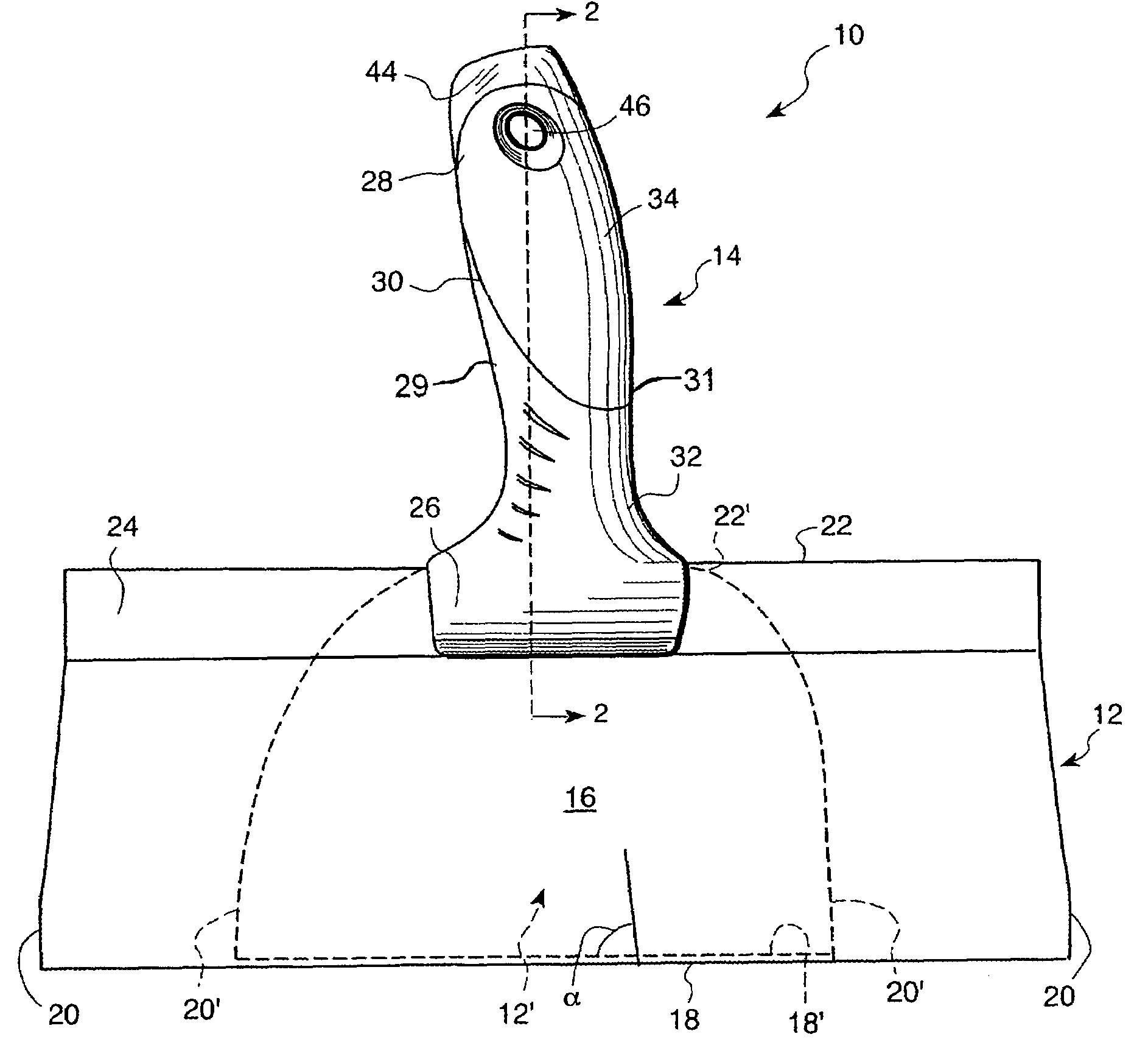
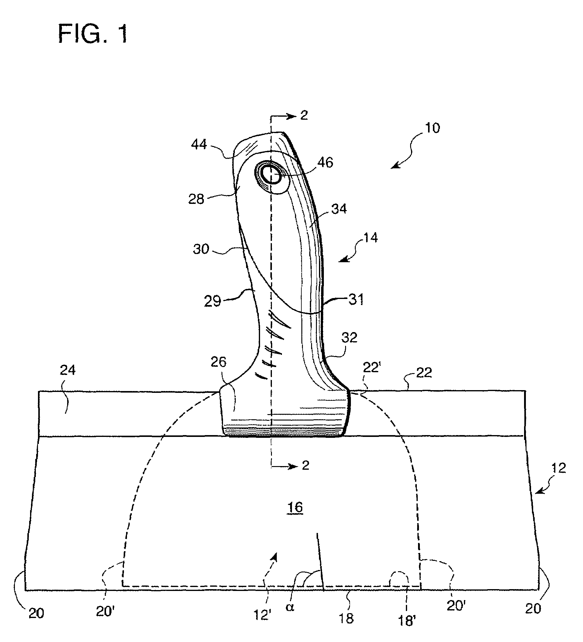
[0012]Referring now to FIG. 1, the present taping knife is generally designated 10. The knife 10 generally includes a blade 12, 12′, and a handle 14.

[0013]The taping knife blade 12, 12′ is made up of a web 16, a working edge 18, 18′, two side edges 20, 20′, and a handle edge 22, 22′ opposite the working edge. Taping knife blades are preferably thin and flexible, and they typically taper in thickness throughout the portions of the blade 12, 12′ with the thickest portion at the handle and the thinnest portion at the end of the blade. The blade 12, 12′ is preferably made from blued steel, but other materials exhibiting similar physical characteristics are contemplated.

[0014]There are generally two styles of blade that are preferred: a blade 12 (shown in solid lines) eight to fourteen inches wide that has side edges 20 (shown in solid lines) composed of substantially straight segments and a handle edge 22 that is nearly as long as the working edge 18, and a blade 12′ (shown in phantom) ...


PUM


Abstract

A taping knife has a web, a working edge, two side edges, and a handle edge opposite the working edge. The handle is connected to the blade to have an angular orientation relative to the working edge of the blade such that the handle is neither parallel nor perpendicular to the blade working edge.

Description

BACKGROUND OF THE INVENTION[0001]The present invention relates generally to hand tools and hand tool handles, and more specifically to taping knives for use in finishing wallboard construction.[0002]Taping knives, which have varying blade widths, are used to finish drywall or wallboard construction projects and create a smooth surface between abutting drywall surfaces. In this application, the terms “taping knife” and “taping tool” are considered interchangeable. After drywall boards are secured to the underlying wall supports, a smaller taping knife (e.g. four to six inches) is generally used to apply settable joint compound and drywall tape to the joints formed by the abutting drywall surfaces. At this stage, unseated nails may also be set into wallboard and supporting studs. After the joint compound dries, progressively larger taping knives (e.g. eight to fourteen inches) are used to apply more compound to the joint areas. This step is repeated, with intermittent sanding steps, u...

Claims


Application Information

Patent Timeline
Patent Type & Authority Patents(United States)
IPC IPC(8): E04F21/16
CPCA47L13/022E04F21/165B25G1/102E04F21/1652B05C17/10
Inventor BRUNO, ROBERTSTERPKA, FRANKMYERS, MATTHEW EARLE
Owner UNITED STATES GYPSUM CO
Why Eureka
Try Eureka