Boring device

a technology of boring device and punching unit, which is applied in the field of punching unit, can solve the problems of many parts of the camera type punching unit, and achieve the effect of reducing the number of sensors and reducing the cost of the punching uni

Inactive Publication Date: 2008-12-02
DAIDO KOGYO CO LTD
View PDF26 Cites 17 Cited by
  • Summary
  • Abstract
  • Description
  • Claims
  • Application Information

AI Technical Summary

Benefits of technology

[0006]Accordingly, since the punching unit is capable of producing the punching state of the predetermined number of holes by reciprocating the reciprocating member (35 or 75) within the first movable range and by vertically moving the punches of the first group through the intermediary of the cams and followers corresponding to the punches of the first group and is capable of producing the punching state of the less holes than the predetermined number by reciprocating the reciprocating member (35 or 75) within the second movable range and by vertically moving the punches of the second group through the intermediary of the cams and followers corresponding to the second group, and since any one of the punches of the first group is contained also in the punches of the second group and the number of punches of the second group is fewer than that of the first group, each punch in the first and second groups may be selectively put into operation corresponding to the movement of the reciprocating member (35 or 75) and it becomes possible to lessen the total number of punches used in the different punching processes to be less than a total number of punches of the first and second groups, while having the functions of two units that carry out the processes of punching different number of holes. Thus, the number of punches and corresponding dies may be reduced as compared to those of the prior art unit. Still more, the number of parts may be reduced, the structure of the unit may be simplified and its cost may be lowered. Accordingly, when this punching unit is mounted to an image forming apparatus such as a copying machine, it can contribute to multi-functioning of the apparatus.
[0008]Accordingly, the reciprocating member (35) may reach the first or second movable range readily and reliably just by moving in one direction or in the other direction from the home position and hence the control may be simplified.
[0012]Accordingly, since this arrangement produces the three-hole punching state in which the common punch (52b) at the center of the first group is positioned at the center and the two-hole punching state in which its center is positioned at the intermediate position between the common punch (52b) and the punch (53) dedicated for punching two holes, the two-hole and three-hole punching processes may be freely carried out to the member to be punched by only four punches (52a through 52c and 53) and dies (54) in total by using the common punch (52b) at the center of the three-hole punches (52a, 52b and 52c) also for punching two holes by shifting the respective centers in correspondence to the respective processes. Thus, it becomes possible to readily switch the process for punching three holes at a certain pitch in the member to be punched and the process for punching two holes at a different pitch.
[0016]Accordingly, since the reciprocating member (75) may readily and reliably reach the first or second movable range just by advancing by one step in one direction from the home position or by advancing further by one step in one direction from the first movable range, the control may be simplified.
[0020]Accordingly, because the first group is composed of the four or more punches, i.e., the even number of punches (89a through 89d), and the second group is composed of the two center punches (89b and 89c) among the punches (89a through 89d) of the first group, the four- and two-hole punching processes may be adequately and freely carried out on a sheet P without shifting, in correspondence to each process, the center of each punching state of the four-punching state which is carried out centering on the center part of the four punches (89a through 89d), i.e., the intermediate position between the punches (89b and 89c), of the first group and of the two-hole punching state which is carried out centering on the intermediate position between the two center punches (89b and 89c) of the first group.
[0022]Accordingly, it becomes possible to reduce a number of sensors for detecting the move of the cam plate (75) by the very simple arrangement of just restricting the move of the cam plate (75) to the movable range on the opposite side by the move restricting means (23). That is, when the punching unit (60) is mounted to a main unit of a copying machine or the like, a control is made so as to be able to use only the group actually used often based on data detected by the sensors for detecting the move of the reciprocating member (75) to the group of the opposite side. For instance, when the control is reset after when a supply of electric power is started again from a condition of system-down such as a power failure, the control of shifting the reciprocating member (75) to the group used before the power failure is normally carried out based on the result detected by the sensor. Accordingly, although the sensor (78) is essential, the present invention enables the relatively expensive sensor (78) to be eliminated and the cost to be cut because it restricts the very move of the reciprocating member (75) to the opposite side by the move restricting means (23) and by omitting the sensor (78).

Problems solved by technology

However, such sliding-cam type punching unit requires many parts because it requires punches and dies each equal to a total number of holes to be punched, e.g., five each punches and dies in the switching type punching unit for punching two and three holes.

Method used


Image

  • Boring device
  • Boring device
  • Boring device

Examples


first embodiment

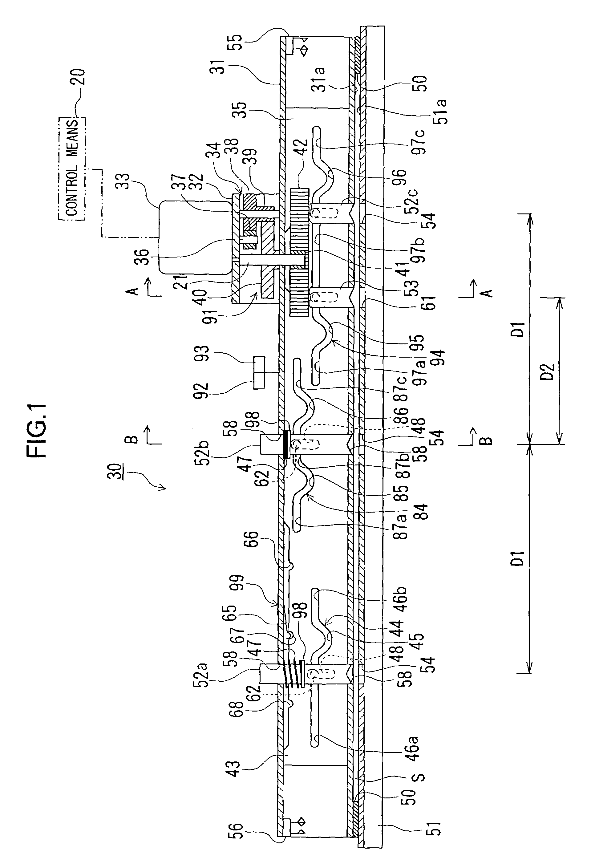
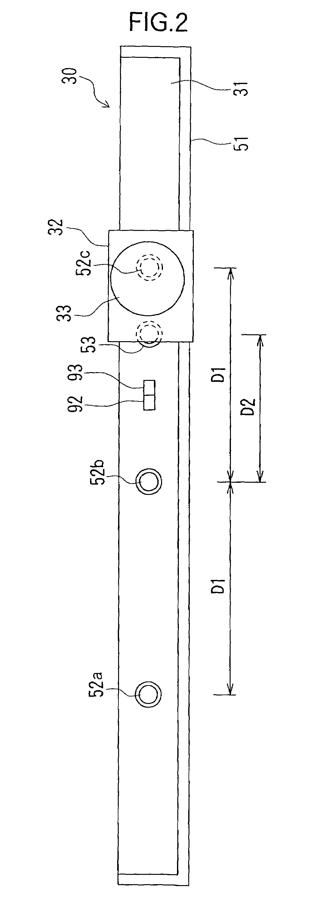
[0037]A first embodiment of an inventive punching unit will be explained below with reference to the drawings. FIG. 1 is a partially broken front view of the punching unit according to the first embodiment of the invention, FIG. 2 is a plan view of the punching unit in FIG. 1, FIG. 3 is a section view of the punching unit taken along a line A-A in FIG. 1, FIG. 4 is a section view of the punching unit taken along a line B-B in FIG. 1 and FIGS. 5A through 5C are section views of the punching unit for explaining operations of the punching unit of the present embodiment.

[0038]As shown in FIGS. 1 and 2, the punching unit 30 of the present embodiment has a rectangle-tubular main frame 31, on which a motor 33 is disposed through an intermediary of a bracket 32. The motor 33 is linked to a lengthy cam plate (reciprocating member) 35 through an intermediary of a speed reducing gear mechanism 34 and functions as a driving source for moving the cam plate 35 in the lateral direction in FIG. 1. ...

second embodiment

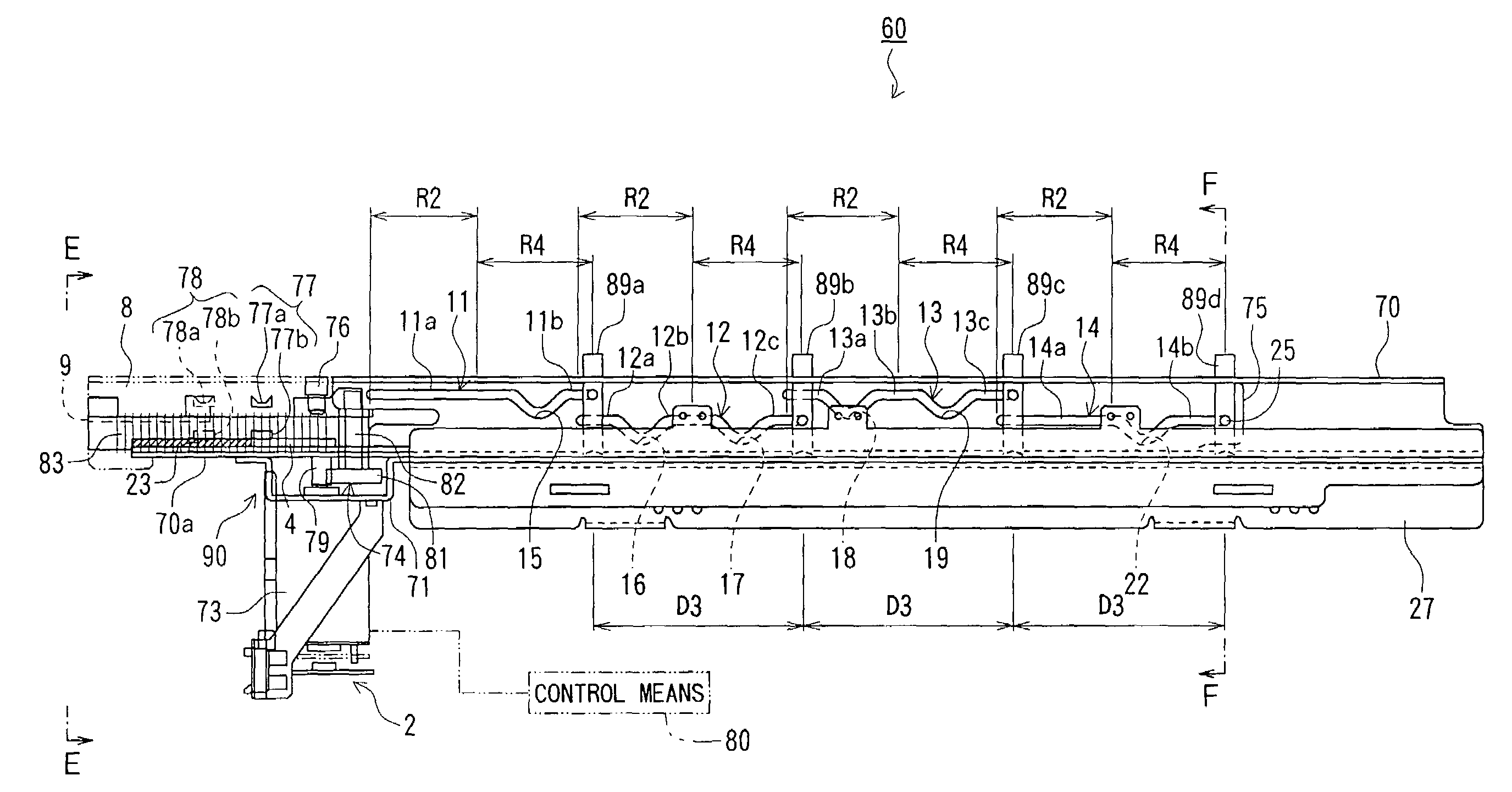
[0087]Next, a second embodiment of the inventive punching unit will be explained with reference to FIGS. 6 through 11. FIG. 6 is a partially broken front view of a punching unit according to a second embodiment of the invention, FIG. 7 is a plan view of the punching unit in FIG. 6, FIG. 8 is a bottom view of the punching unit in FIG. 6, FIG. 9 is a side view of the punching unit taken along a line E-E in FIG. 6, FIG. 10 is a side section view of the punching unit taken along a line F-F in FIG. 6 and FIG. 11 is a partially enlarged front view of a movable range detecting sensor, a rack and others in FIG. 6.

[0088]As shown in FIGS. 6 through 11, the punching unit 60 of the present embodiment is provided with a motor 73 on a main frame 70 through an intermediary of a bracket 71. The motor 73 is linked to a lengthy cam plate (reciprocating member) 75 through the intermediary of a speed reducing gear mechanism 74 and functions as a driving source for moving the cam plate 75 in the lateral...


PUM

PropertyMeasurementUnit
electric poweraaaaaaaaaa
diameteraaaaaaaaaa
rotational forceaaaaaaaaaa

Abstract

A punching unit is arranged so that a plurality of punches is grouped into a first group having a predetermined number of punches and a second group containing any one of the punches in the first group and having a smaller number of punches. A punching state of the predetermined number of punches is produced by reciprocating a reciprocating member within a first range and by vertically moving the punches of the first group through the intermediary of cams and followers corresponding to the first group and another punching state of the smaller number of punches is reached by reciprocating the reciprocating member within a second movable range and vertically moving the punches of the second group through the intermediary of cams and followers corresponding to the second group. This arrangement allows the number of punches and dies to be reduced as compared to the prior art.

Description

TECHNICAL FIELD[0001]The present invention relates to a punching unit for punching holes in a sheet type member by engaging punches with corresponding dies and more specifically to a punching unit which may be most suitably attached to a main unit of an image forming apparatus, such as a copying machine, a printer, a facsimile and a multifunction machine of those machines, or to a printing machine.BACKGROUND ART[0002]Hitherto, as a punching unit of the sort described above, there have been known a dedicated type punching unit dedicated for punching two holes, three holes or four holes and a switching type punching unit arranged so as to be able to commonly use punches in punching two holes and three holes or two holes and four holes. As the switching type punching unit, there is known a sliding-cam type punching unit wherein a stroke range of a cam is divided into two stages so as to be able to punch two holes in a certain stroke range and to punch three holes in another stroke rang...

Claims


Application Information

Patent Timeline
Patent Type & Authority Patents(United States)
IPC IPC(8): B26F1/04B26F1/14B26D5/16B26F1/36
CPCB26D5/16B26F1/04B26F1/36Y10T83/8727Y10T83/943
Inventor MAJIMA, TOSHIYUKINISHIMURA, KAZUO
Owner DAIDO KOGYO CO LTD
Why Eureka
Try Eureka