Pipe clamp with integral latch
a technology of integral latch and pipe clamp, which is applied in the direction of hose connection, coupling, machine/engine, etc., can solve the problems of waste, less efficiency, and disruption of the assembly process, so as to facilitate the multi-directional assembly of the two components, minimize the possibility of damage to the clip, and minimize the effect of assembly errors
- Summary
- Abstract
- Description
- Claims
- Application Information
AI Technical Summary
Benefits of technology
Problems solved by technology
Method used
Image
Examples
first embodiment
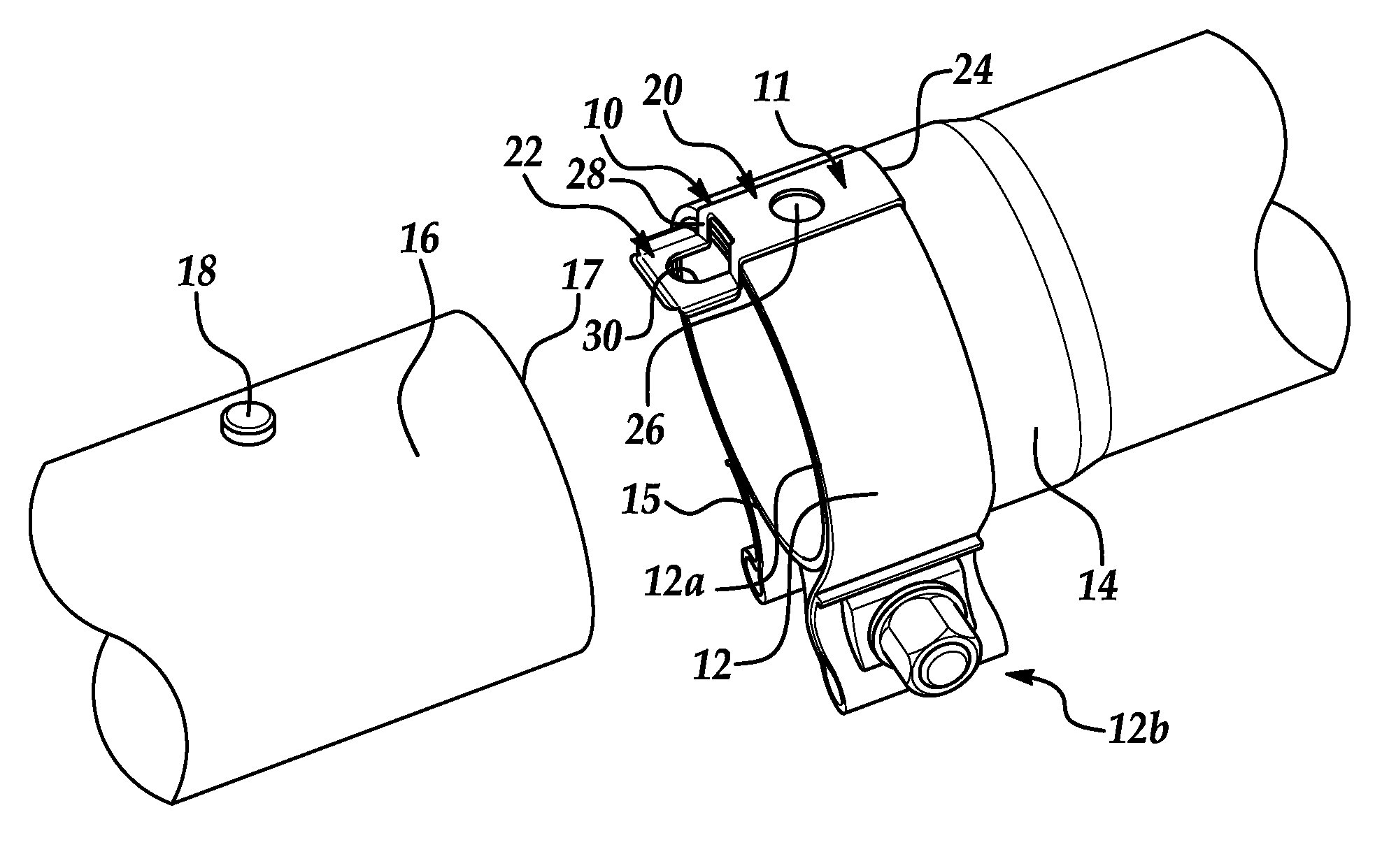
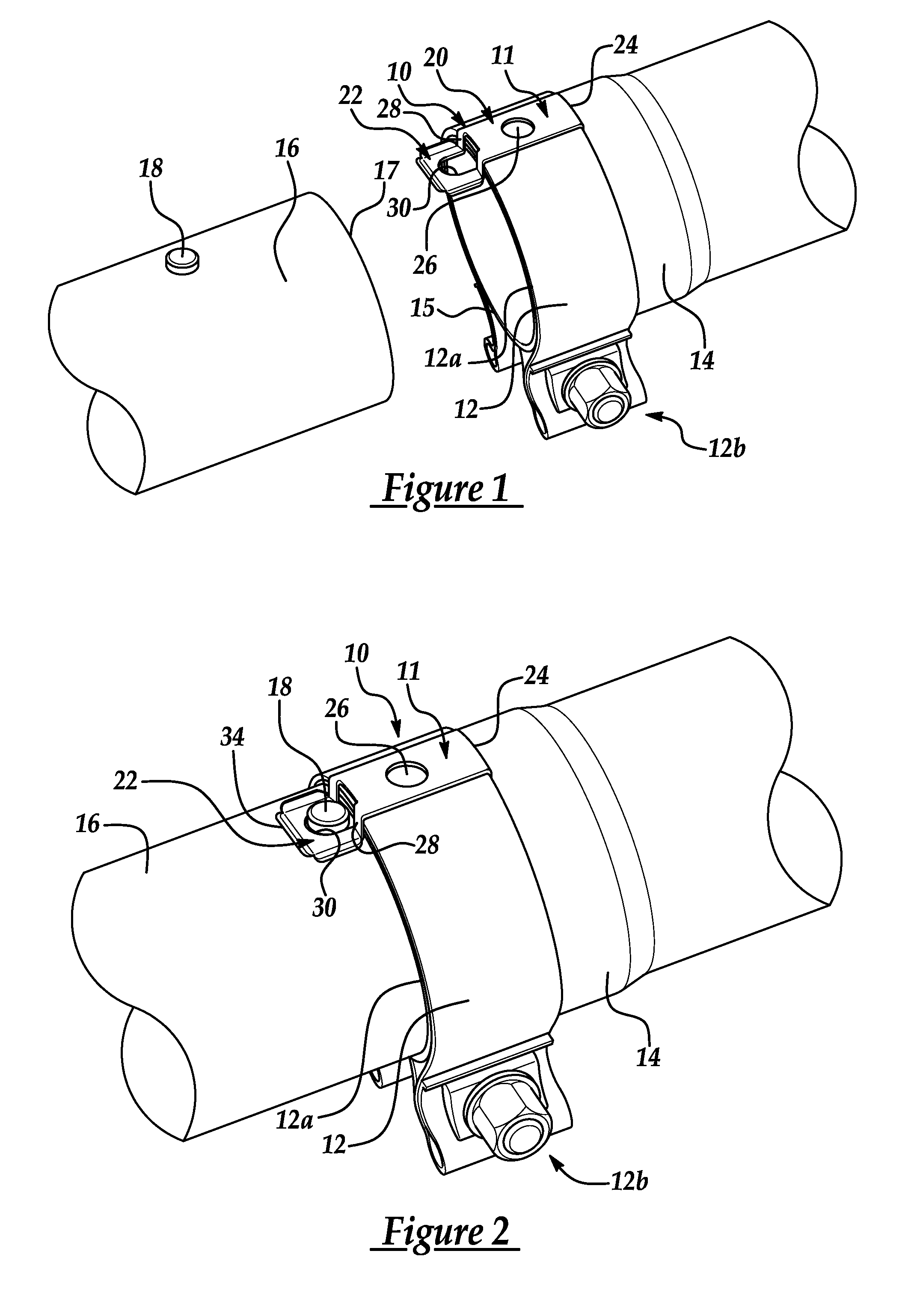
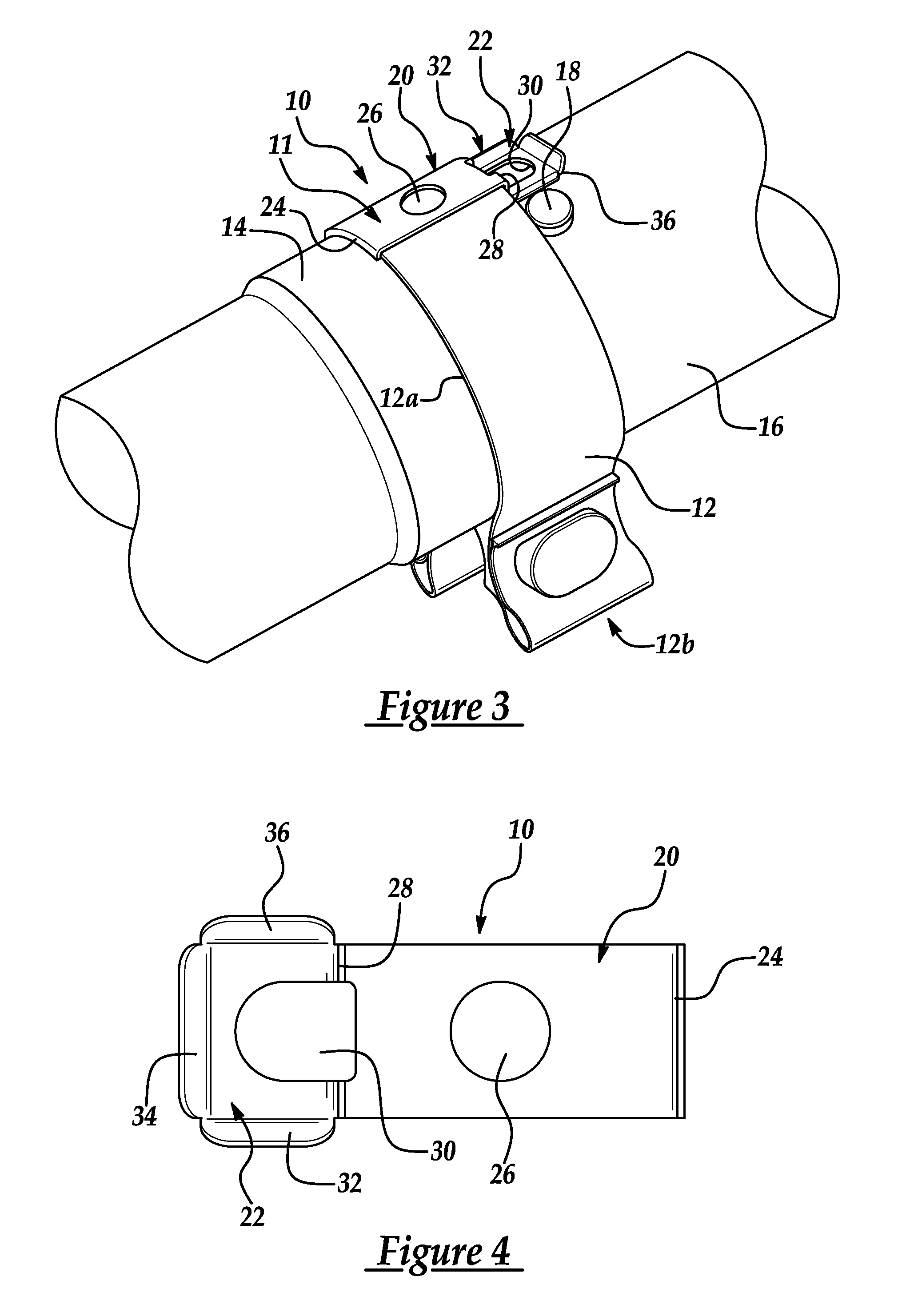
[0027]FIG. 1 shows a band clamp 12 and its integral latch 10 in accordance with the present invention. Latch 10 is shown secured to band clamp 12 which can be done as a part of original manufacturing of the band clamp 12 prior to its use. Clamp 12 with its latch 10 is securely attached by, for example, a spot weld, to an end of a first exhaust pipe 14, and the latch 10 is used to temporarily secure the band clamp 12 and attach first pipe 14 to a second exhaust pipe 16 in a desired configuration by snapping over a button 18 that is pre-formed or pre-attached to the second pipe 16, as shown in FIG. 2. This temporary connection properly locates the two pipe ends together and allows clamp 12 to be subsequently tightened without the installer or a second person having to separately hold the pipe ends together during tightening. As shown in FIGS. 1-3, button 18 is a cylindrical protrusion located on the outer surface of pipe 16; however, as used herein and in the claims, “button” refers b...
fourth embodiment
[0044]FIGS. 11 and 12 show the present invention using a latch / clip arrangement that is similar to that of FIGS. 9 and 10, but is different primarily in that a pipe coupler 412 is used in combination with two substantially equal-diameter pipes 114, 116 that are brought together in coaxial alignment to form a butt joint. It also differs in that, like the band clamp 212 of FIGS. 7 and 8, the pipe coupler 412 is a separate component that is connected to each pipe 114, 116 via an interlocking feature or button 119, 118 located near the pipe ends 115, 117, respectively. Except as noted below, pipe coupler 412 can be made as shown and described in U.S. Patent Application Publication No. 2002 / 0014772 A1, published Feb. 7, 2002, the entire content of which is hereby incorporated by reference.
third embodiment
[0045]Pipe coupler 412 has a latch 410 that includes a base 420, a first clip 422, and a second clip 423. Clip 422 and clip 423 are set apart vertically from base 420 by a first step 428 and a second step 429, respectively. Clip 422 includes a first interlocking feature or retention finger 438 and clip 423 includes a second interlocking feature or retention finger 439. Clip 422 and finger 438 are structured and function similarly to clip 322 and finger 338 in the third embodiment and this description thus will not be repeated. Likewise, clip 423 and finger 439 are a mirror image of clip 422 and finger 438. Steps 428 and 429 facilitate vertical flexibility of clips 422 and 423 and also need not be necessary. Latch 410 is stamped from a unitary piece of sheet metal and is generally rectangular in cross-sectional shape. The latch can be welded to the band of the pipe coupler 412 at a welding area 411.
[0046]As is evident from FIG. 12, latch 410 has approximately the same length—from fin...
PUM
| Property | Measurement | Unit |
|---|---|---|
| acute angle | aaaaa | aaaaa |
| angle | aaaaa | aaaaa |
| relative rotational movement | aaaaa | aaaaa |
Abstract
Description
Claims
Application Information
 - R&D
- Intellectual Property
- Life Sciences
- Materials
- Tech Scout
- Unparalleled Data Quality
- Higher Quality Content
- 60% Fewer Hallucinations
Browse by: Latest US Patents, China's latest patents, Technical Efficacy Thesaurus, Application Domain, Technology Topic, Popular Technical Reports.
© 2025 PatSnap. All rights reserved.Legal|Privacy policy|Modern Slavery Act Transparency Statement|Sitemap|About US| Contact US: help@patsnap.com


