Pipe clamp with integral latch

a technology of integral latch and pipe clamp, which is applied in the direction of hose connection, coupling, machine/engine, etc., can solve the problems of waste, less efficiency, and disruption of the assembly process, so as to facilitate the multi-directional assembly of the two components, minimize the possibility of damage to the clip, and minimize the effect of assembly errors

Active Publication Date: 2005-05-12
NORMA US HOLDING LLC
View PDF32 Cites 65 Cited by
  • Summary
  • Abstract
  • Description
  • Claims
  • Application Information

AI Technical Summary

Benefits of technology

[0009] According to another preferred exemplary embodiment, the present invention may be utilized in the form of a pipe coupler wherein the pipes are connected together by the clamp with their ends abutted together. The interlocking feature can be provided on one or both pipes and one or both axial ends of the pipe coupler. Where the pipe coupler is configured to be loosely attached to both pipe ends via interlocking features, a single latch having a clip at each opposite end can be used. The clips can extend past the end of the pipe coupler to engage the buttons or other interlocking features on the pipes. Alternatively, the pipe coupler can have a notch at one or both axial ends to receive the buttons, with the clips being substantially flush with the axial ends to minimize the possibility of damage to the clips during shipping and handling. Where the pipe coupler includes a split sealing sleeve, the sleeve can also be notched at the same location(s) as the outer band of the coupler.
[0010] In any of the embodiments, the interlocking feature of each clip preferably, but need not, includes at least one slanted or up-turned edge forming a bearing surface that allows the clip to ride up o

Problems solved by technology

When this happens, the assembly process is disrupted and consequently becomes less efficient.
In lap joints, if the pipe ends are overlapped too far, the excess pipe material becomes waste.
Conversely, i

Method used


Image

  • Pipe clamp with integral latch
  • Pipe clamp with integral latch
  • Pipe clamp with integral latch

Examples


first embodiment

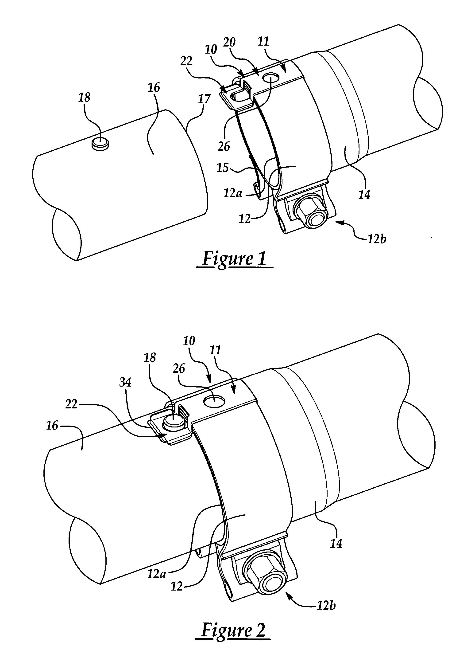
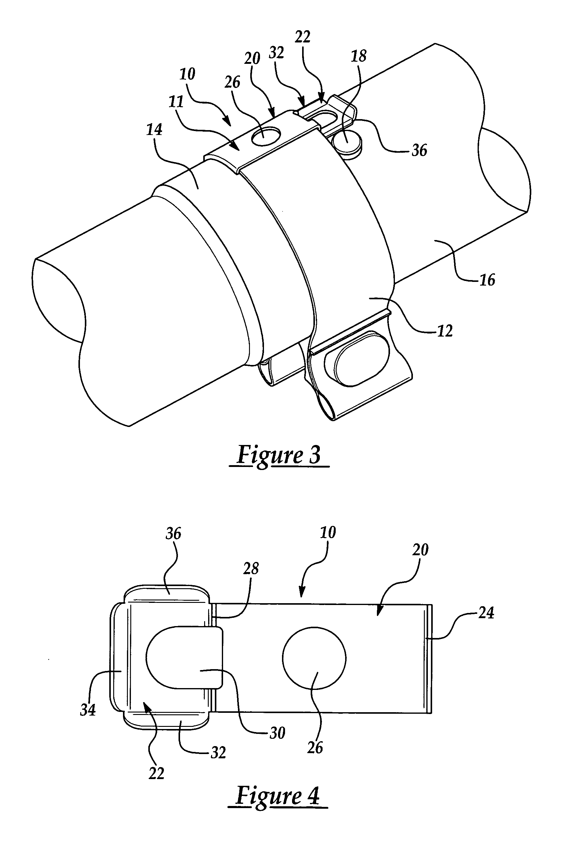
[0027]FIG. 1 shows a band clamp 12 and its integral latch 10 in accordance with the present invention. Latch 10 is shown secured to band clamp 12 which can be done as a part of original manufacturing of the band clamp 12 prior to its use. Clamp 12 with its latch 10 is securely attached by, for example, a spot weld, to an end of a first exhaust pipe 14, and the latch 10 is used to temporarily secure the band clamp 12 and attach first pipe 14 to a second exhaust pipe 16 in a desired configuration by snapping over a button 18 that is pre-formed or pre-attached to the second pipe 16, as shown in FIG. 2. This temporary connection properly locates the two pipe ends together and allows clamp 12 to be subsequently tightened without the installer or a second person having to separately hold the pipe ends together during tightening. As shown in FIGS. 1-3, button 18 is a cylindrical protrusion located on the outer surface of pipe 16; however, as used herein and in the claims, “button” refers b...

fourth embodiment

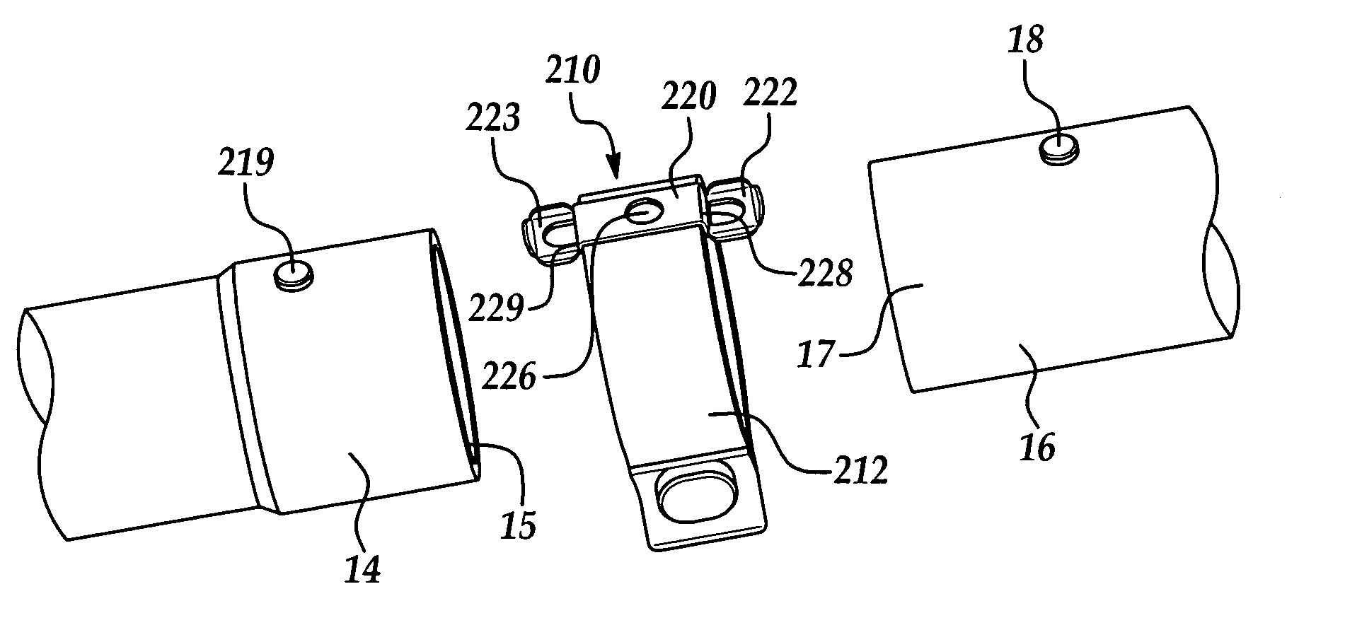
[0044]FIGS. 11 and 12 show the present invention using a latch / clip arrangement that is similar to that of FIGS. 9 and 10, but is different primarily in that a pipe coupler 412 is used in combination with two substantially equal-diameter pipes 114, 116 that are brought together in coaxial alignment to form a butt joint. It also differs in that, like the band clamp 212 of FIGS. 7 and 8, the pipe coupler 412 is a separate component that is connected to each pipe 114, 116 via an interlocking feature or button 119, 118 located near the pipe ends 115, 117, respectively. Except as noted below, pipe coupler 412 can be made as shown and described in U.S. Patent Application Publication No. 2002 / 0014772 A1, published Feb. 7, 2002, the entire content of which is hereby incorporated by reference.

third embodiment

[0045] Pipe coupler 412 has a latch 410 that includes a base 420, a first clip 422, and a second clip 423. Clip 422 and clip 423 are set apart vertically from base 420 by a first step 428 and a second step 429, respectively. Clip 422 includes a first interlocking feature or retention finger 438 and clip 423 includes a second interlocking feature or retention finger 439. Clip 422 and finger 438 are structured and function similarly to clip 322 and finger 338 in the third embodiment and this description thus will not be repeated. Likewise, clip 423 and finger 439 are a mirror image of clip 422 and finger 438. Steps 428 and 429 facilitate vertical flexibility of clips 422 and 423 and also need not be necessary. Latch 410 is stamped from a unitary piece of sheet metal and is generally rectangular in cross-sectional shape. The latch can be welded to the band of the pipe coupler 412 at a welding area 411.

[0046] As is evident from FIG. 12, latch 410 has approximately the same length—from f...


PUM

PropertyMeasurementUnit
Lengthaaaaaaaaaa
Flexibilityaaaaaaaaaa
Conformationaaaaaaaaaa

Abstract

A pipe clamp that enables two pipes to be loosely connected together in a desired axially-aligned and rotationally-aligned configuration prior to tightening of the clamp. The pipe clamp includes a band having a first end and a second end, and a tightening mechanism connected to the band for drawing the ends of the band together. The pipe clamp further includes a latch having a base portion attached to the band and a clip portion that snaps over a button welded to the pipe to temporarily hold the clamp in place on the pipe. In some embodiments the pipe clamp is connected to both pipes via an attached clip and buttons at each axial end of the clamp, and in other embodiments the clamp is welded to one pipe and the clip and button then being used to loosely connect the welded assembly to the other pipe.

Description

CROSS-REFERENCE TO RELATED APPLICATION [0001] This application claims the priority of U.S. Application No. 60 / 518,133, filed Nov. 7, 2003, the complete disclosure of which is hereby incorporated by reference.TECHNICAL FIELD [0002] This invention relates to pipe clamps for securing pipes together and to techniques for loosely securing a pipe clamp to pipe ends in a desired configuration prior to tightening of the clamp. BACKGROUND OF THE INVENTION [0003] Automotive exhaust pipes are typically routed along the underbody of a vehicle and may take winding paths between the exhaust manifold, catalytic converter, and muffler depending upon the design and location of other components of the vehicle. In order to avoid obstructions and for underbody packaging purposes, it is often necessary for the exhaust pipe to include one or more bends along its length. Such exhaust pipes can be manufactured in separate sections between at least some of the bends, positioned in an end-to-end axial config...

Claims


Application Information

Patent Timeline
IPC IPC(8): F16L21/06
CPCF01N13/1805F01N2450/18Y10T24/1441F16L21/065Y10T24/1451F01N2450/24F16L21/005F16L55/00
Inventor CASSEL, SCOTT T.AMEDURE, MICHAEL E.IGNACZAK, BRIAN T.
Owner NORMA US HOLDING LLC
Why Eureka
Try Eureka