
Liquid ejection apparatus and liquid filling method for liquid ejection apparatus

a liquid ejection and liquid filling technology, applied in printing and other directions, can solve the problems of difficult to remove bubbles (an air layer) difficult to completely fill the supply line with liquid, and difficult to remove bubbles from the enlarged portion. , to achieve the effect of efficient liquid filling

Inactive Publication Date: 2008-12-02
SEIKO EPSON CORP
View PDF11 Cites 15 Cited by
  • Summary
  • Abstract
  • Description
  • Claims
  • Application Information

AI Technical Summary

Benefits of technology

The present invention provides a liquid ejection apparatus and method for efficiently charging the supply line with liquid without wasting an excessive amount of liquid. The method includes a first suction step of performing suction by holding a portion of the supply line in a blocked state and then releasing the blocked portion, which allows for the efficient removal of bubbles from the supply line. The apparatus includes a supply line with enlarged portions that communicate with the tubular passage, which makes it difficult to remove bubbles from the enlarged portions. The second suction step is performed to obtain the maximum negative pressure that is lower than the first suction step, which allows for the efficient reduction of bubbles trapped in the downstream enlarged portions. The apparatus also includes an open-close device for selectively opening and closing a portion of the supply line and a controller for controlling the open-close device and the suction device.

Problems solved by technology

The structure of each enlarged portion in the supply line makes it difficult to remove bubbles (an air layer) from the enlarged portion.
It is rarely possible to completely fill the supply line with the liquid through a single cycle of suction.
However, after a certain time, a stationary flow may occur in the vicinity of the bubbles, making it difficult to further remove the bubbles from the enlarged portions.

Method used


Image

  • Liquid ejection apparatus and liquid filling method for liquid ejection apparatus
  • Liquid ejection apparatus and liquid filling method for liquid ejection apparatus
  • Liquid ejection apparatus and liquid filling method for liquid ejection apparatus

Examples


second embodiment

[0083]A second embodiment of the present invention will hereafter be explained with reference to FIG. 7. The mechanical configuration of the second embodiment is identical with that of the first embodiment. Same or like reference numerals are given to parts of the second embodiment that are the same as or like corresponding parts of the first embodiment. Description thereof thus will be omitted. The second embodiment is different from the first embodiment in terms of the second intense suction.

[0084]More specifically, in the first intense suction of the second embodiment, the controller 41 controls the suction pump 23 at a suction speed V1 that is equal to that of the first intense suction of the first embodiment. The suction pump 23 is continuously operated. Contrastingly, in the second intense suction, the controller 41 controls and continuously operates the suction pump 23 at a suction speed V2 (1) that is lower than the speed V1 of the first intense suction.

[0085]The time (the c...


PUM


Abstract

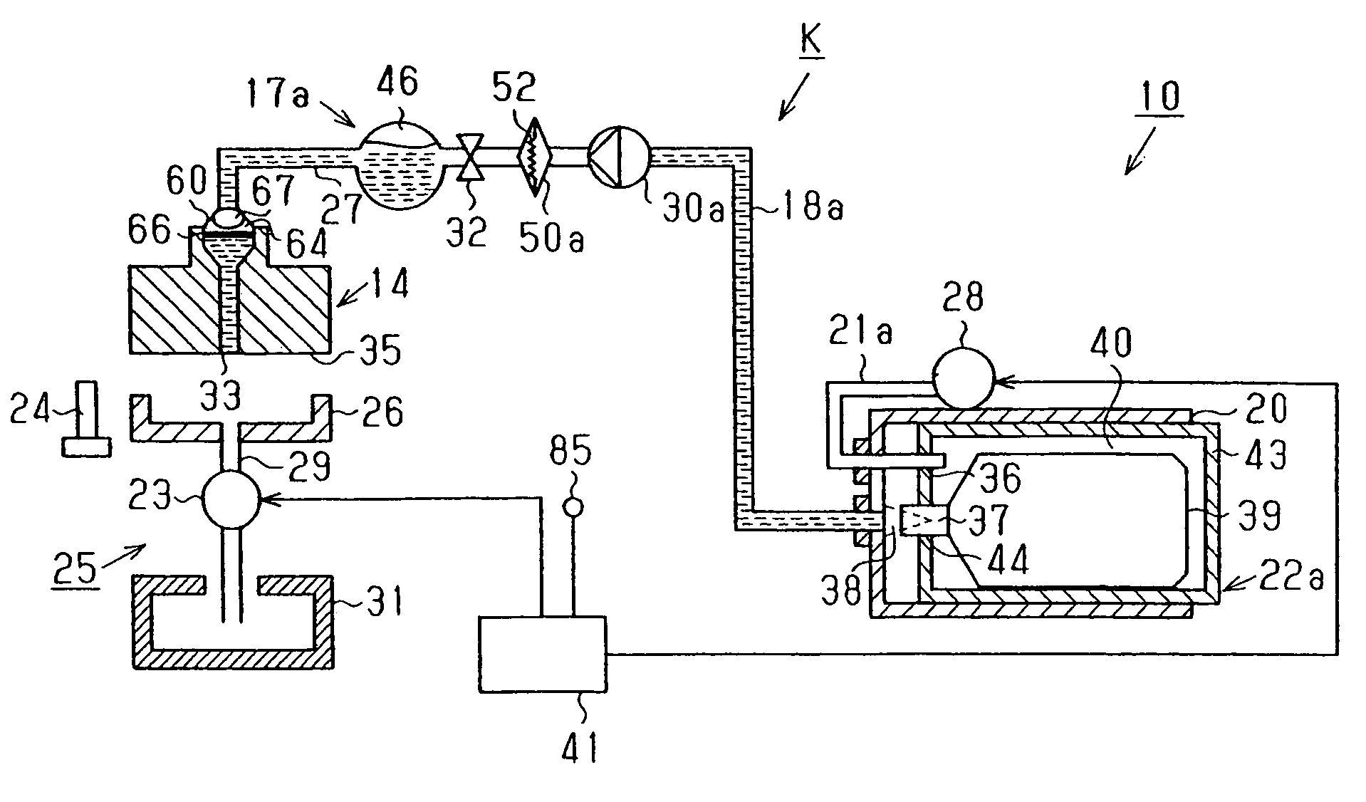
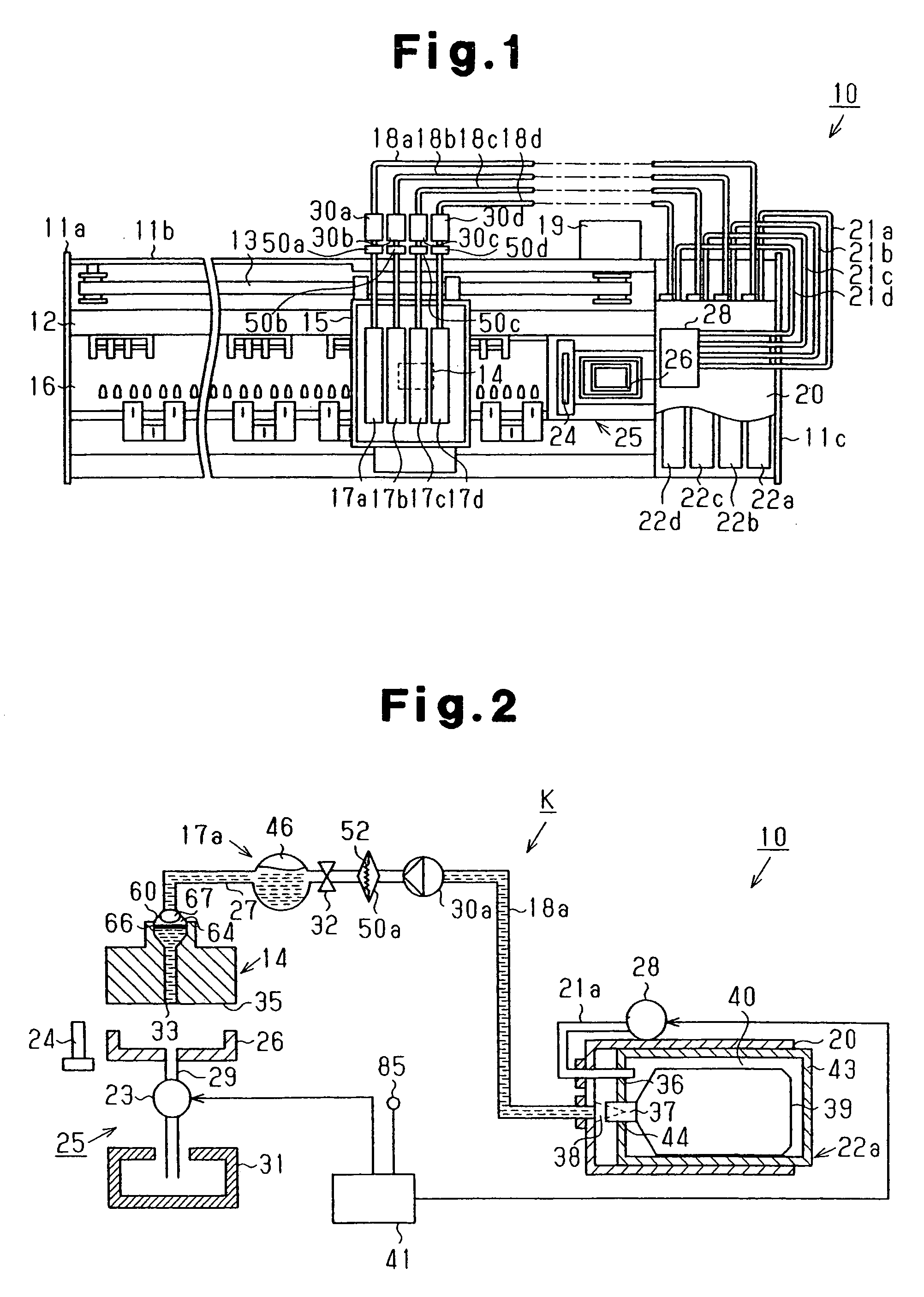
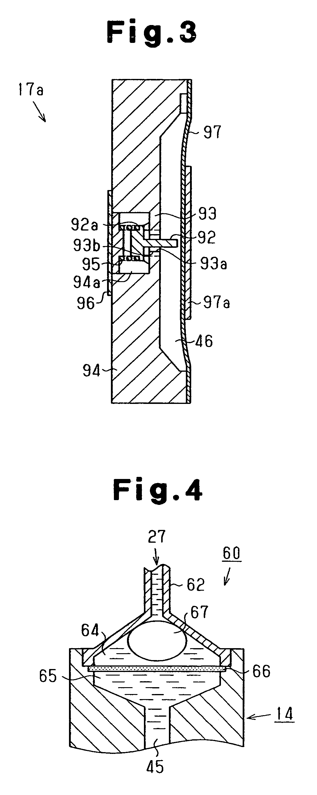
In a first intense suction, a supply line K is subjected to suction by a suction pump 23 with a portion of the supply line K held in a blocked state. Subsequently, the blocked portion of the supply line K is opened and trapped bubbles are discharged from a pressure chamber 46, which is located relatively upstream. In a subsequent second intense suction, the suction by the suction pump 23 is performed on the supply line K with a portion of the supply line K held in a blocked state, until a maximum negative pressure smaller than a maximum negative pressure of the first intense suction is obtained. The blocked portion of the supply line K is then opened, thus discharging trapped bubbles from an upper filter chamber 64, which is located relatively downstream.

Description

BACKGROUND OF THE INVENTION[0001]The present invention relates to liquid ejection apparatuses ejecting liquid as droplets through liquid ejection heads, such as inkjet recording apparatuses, display manufacturing apparatuses, electrode manufacturing apparatuses, and biochip manufacturing apparatuses, and liquid filling methods for these apparatuses.[0002]Conventionally, inkjet printers are known as liquid ejection apparatuses that eject liquid droplets through nozzles of an ejection head. There are some inkjet printers (hereinafter, “printers”) that include “off-carriage” type ink supply systems. One such system includes an ink retainer retaining the ink as liquid that is installed outside a carriage of the printer.[0003]As described in Japanese Laid-Open Patent Publication No. 2003-211688, for example, the ink supply system may include an ink supply line that extends from an ink cartridge to an ejection head formed in the carriage. The supply line includes a pressure adjustment mec...

Claims


Application Information

Patent Timeline
Patent Type & Authority Patents(United States)
IPC IPC(8): B41J2/175B41J2/165
CPCB41J2/17596B41J2/19
Inventor MOMOSE, KAORU
Owner SEIKO EPSON CORP
Learn More