
Monitoring lens apparatus and monitoring camera

a technology of monitoring lens and monitoring camera, which is applied in the direction of instruments, television systems, optical elements, etc., can solve the problems that the focus and zoom cannot be adjusted simply and conveniently, and achieve the effect of easy adjustment of focus and zoom

Inactive Publication Date: 2008-12-02
FUJI PHOTO OPTICAL CO LTD
View PDF8 Cites 8 Cited by
  • Summary
  • Abstract
  • Description
  • Claims
  • Application Information

AI Technical Summary

Benefits of technology

"The present invention provides a monitoring lens apparatus and a monitoring camera with improved focus and zoom capabilities. The lens apparatus includes a fixed cylinder, a first lens frame, a second lens frame, a first ring, a second ring, and an extended portion. The first lens frame and the second lens frame are both movable in the optical axis direction. The first ring is pivotably fixed to the fixed cylinder and is provided with a cam for driving the first lens frame. The second ring is pivotably fixed to the fixed cylinder on the object side of the first ring and is provided with a cam for driving the second lens frame. The extended portion is integrally formed with the first ring and extends to the object side to cover the outer periphery of the second ring. The monitoring camera includes a transparent case member and a cover member covering the lens apparatus. The technical effects of the invention include improved focus and zoom capabilities, simplified operation, and improved durability."

Problems solved by technology

Therefore, it is difficult to insert the finger tip to the peripheries of the focus ring 112, the zoom ring 114, and thus focus and zoom cannot be adjusted simply and conveniently.

Method used


Image

  • Monitoring lens apparatus and monitoring camera
  • Monitoring lens apparatus and monitoring camera
  • Monitoring lens apparatus and monitoring camera

Examples


Embodiment Construction

[0043]Although the invention will be described below with reference to the exemplary embodiments thereof, the following exemplary embodiments and modifications do not restrict the invention.

[0044]According to an exemplary embodiment of the invention, there can be provided a monitoring lens apparatus and a monitoring camera which are novel and improved capable of easily adjusting the focus, the zoom.

[0045]An exemplary embodiment of the invention will be explained in details in reference to the attached drawings as follows. Further, in the specification and the drawings, with regard to constituent elements having essentially the same functions and constitutions, a duplicated explanation will be omitted by attaching the same notations thereto.

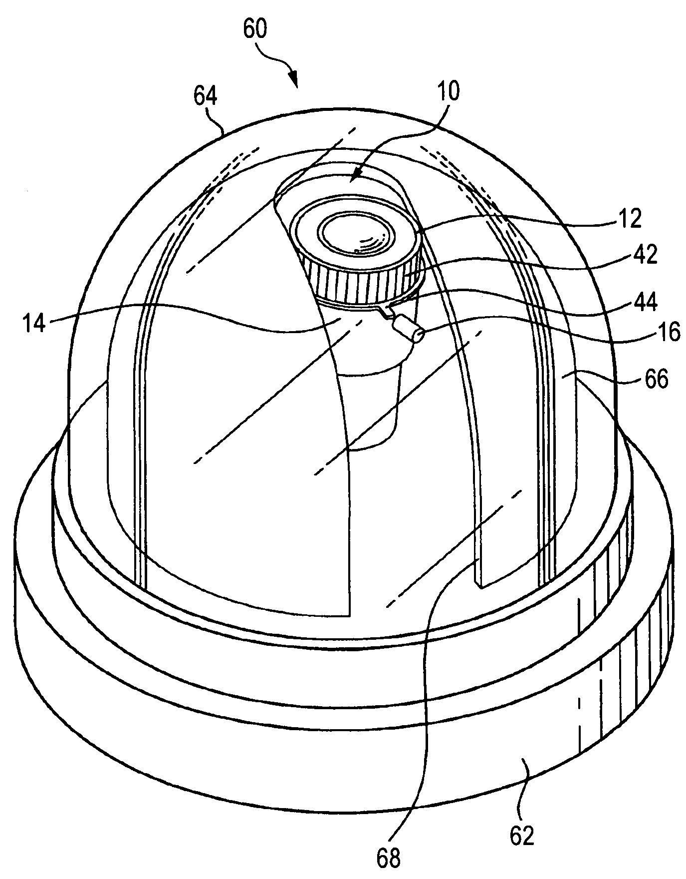
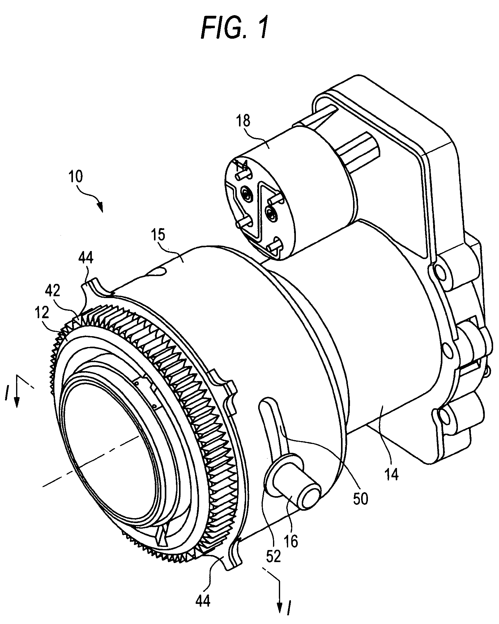
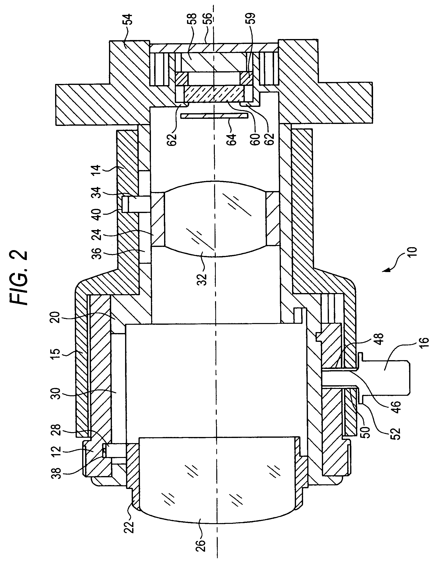
[0046]FIG. 1 is a schematic view showing constitutions of a monitoring lens apparatus 10 according to an exemplary embodiment of the invention and a periphery thereof. The monitoring lens apparatus 10 is mainly used for a monitoring camera as desc...


PUM


Abstract

A monitoring lens apparatus is provided and includes a fixed cylinder, a first lens frame provided at an inner portion of the fixed cylinder and movable in an optical axis direction, a second lens frame provided at the inner portion of the fixed cylinder and movable in the optical axis direction, a first ring provided rotatably to the fixed cylinder and provided with a cam groove for driving the first lens frame, a second ring provided rotatably to the fixed cylinder on an object side of the first ring and provided with a cam groove for driving the second lens frame, and an extended portion provided integrally with the first ring and extended to the object side to cover an outer periphery of the second ring.

Description

BACKGROUND OF THE INVENTION[0001]1. Field of the Invention[0002]The present invention relates to a monitoring lens apparatus and a monitoring camera.[0003]2. Description of Related Art[0004]In recent times, in, for example, financial institutions, stores for selling commodities and the like, a monitoring camera (monitoring CCTV camera) is widely used. Particularly, in recent years, a demand for a dome type small-sized monitoring camera is increasing.[0005]FIG. 4 is a perspective view showing a dome type monitoring camera 100. Further, FIG. 5 is a sectional view showing a state of attaching the monitoring camera 100 to a ceiling. As shown by FIG. 4 and FIG. 5, the monitoring camera 100 is provided with a dome-like outlook, and includes a base 102, a transparent case member 104, and a monitoring lens apparatus 106 arranged at an inner portion of the case member 104. As shown by FIG. 5, the monitoring lens apparatus 106 is attached to the base 102 to be able to make an angle θ variable...

Claims


Application Information

Patent Timeline
Patent Type & Authority Patents(United States)
IPC IPC(8): G02B7/02
CPCG02B7/10G08B13/19619G08B13/1963H04N5/2251H04N5/23238H04N23/55H04N23/698H04N7/18
Inventor AIBA, DAIGOYOSHIDA, SHIGERU
Owner FUJI PHOTO OPTICAL CO LTD
Learn More