

Auto-adjusting sound masking system and method
a masking system and auto-adjusting technology, applied in the direction of sound producing devices, transducer circuits, speech analysis, etc., can solve the problem of laborious trial and error methods
- Summary
- Abstract
- Description
- Claims
- Application Information
AI Technical Summary
Benefits of technology
Problems solved by technology
Method used
Image

Examples
Embodiment Construction
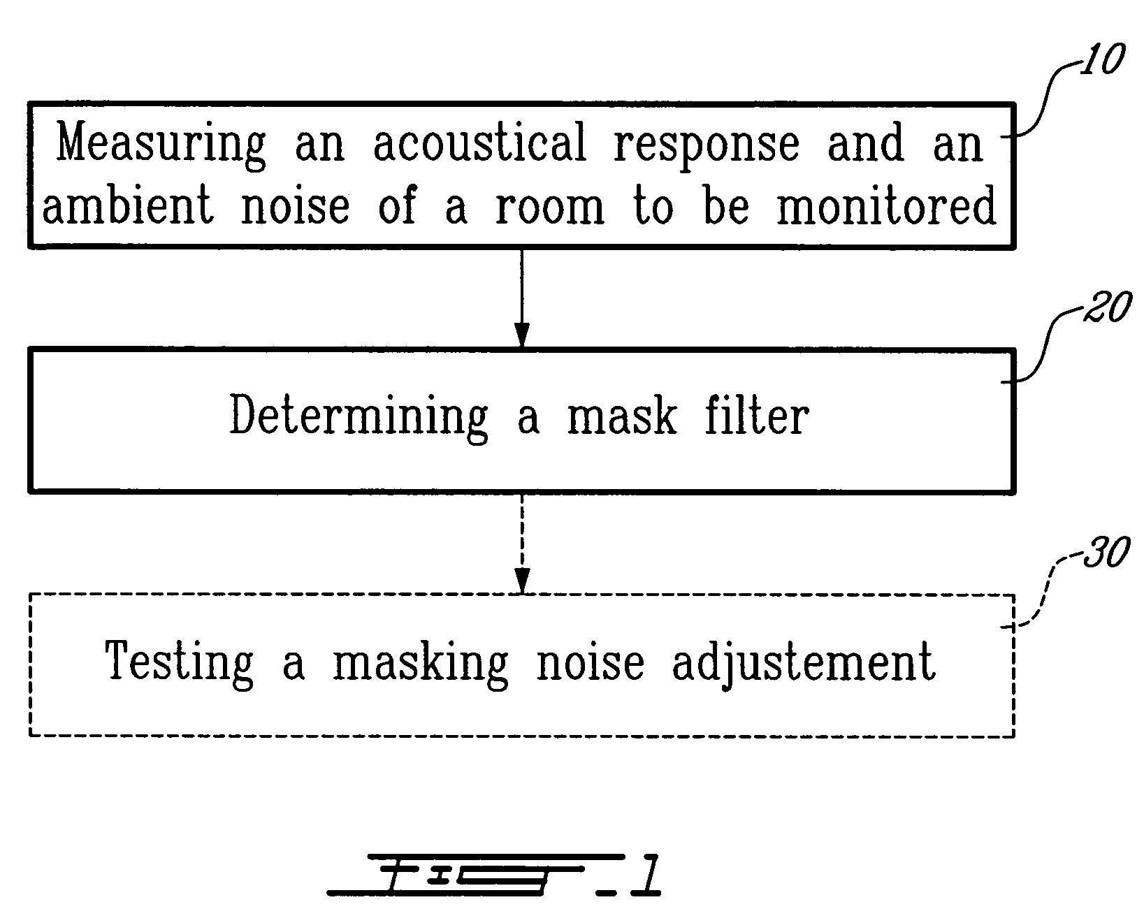
[0022]As illustrated in FIG. 1 of the appended drawings, a method according to a first aspect the present invention generally comprises measuring an acoustical response and an ambient noise of a room to be monitored (step 10); and
[0023]determining a mask filter (step 20). A step of testing auto-adjustment of a masking noise generated through the mask filter determined in step 20 may be further contemplated (step 30).
[0024]In step 10, the acoustical response and the ambient noise of the room to be monitored are measured so as to determine the acoustical characteristics of the room in an emission frequency band of a target masking noise.
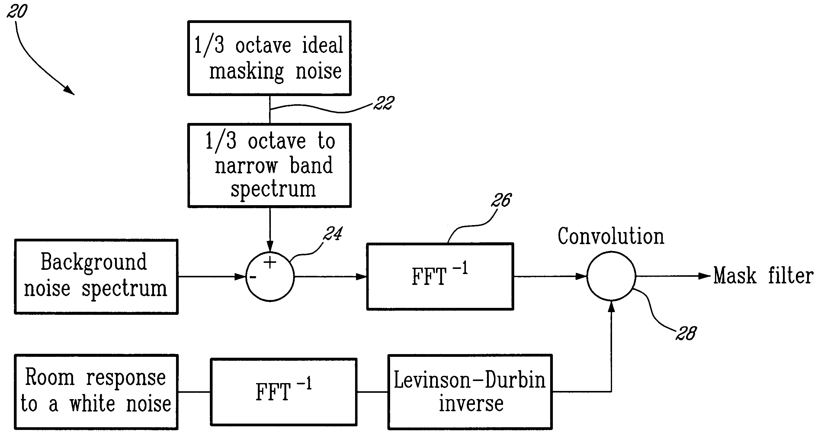
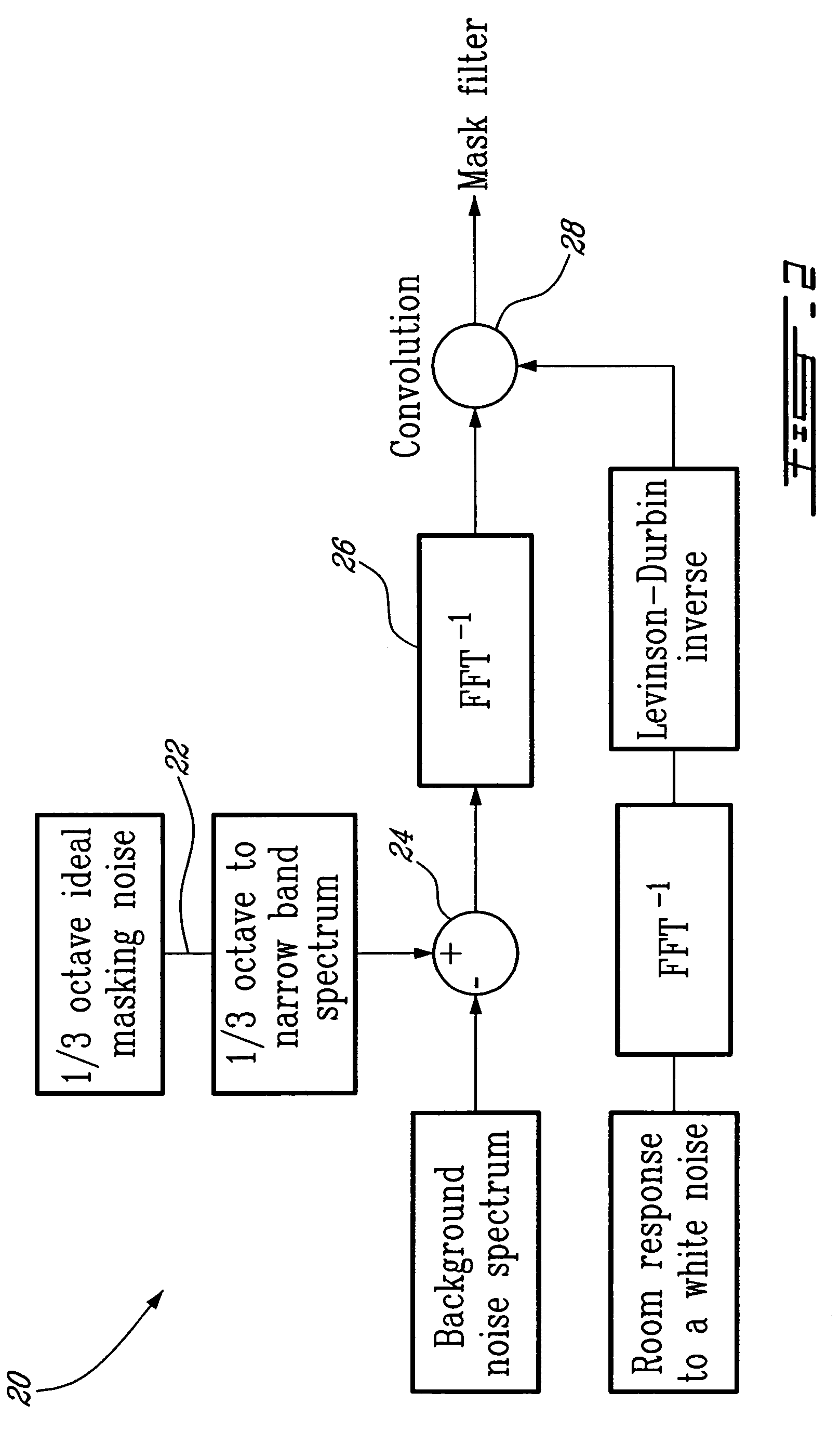
[0025]In step 20, a correction filter (line 42FIG. 3) to be applied to the measured acoustical response (line 40FIG. 3) of the room in order to yield a flat frequency response (line 44FIG. 3) in an emission frequency band of the target masking noise is determined, thereby allowing overcoming this acoustical response of the room.
[0026]More precisely, as...
PUM
 Abstract
Description
Claims
Application Information