Current sensor

a current sensor and sensor technology, applied in voltage/current isolation, voltage/current conversion, instruments, etc., can solve the problems of increasing the risk of electrical noise generation, so as to reduce the electric resistance, increase the heat dissipation characteristic, and reduce the effect of electric resistan

Active Publication Date: 2008-12-09
TDK CORPARATION
View PDF26 Cites 27 Cited by
  • Summary
  • Abstract
  • Description
  • Claims
  • Application Information

AI Technical Summary

Benefits of technology

[0008]The present invention has been achieved in consideration of such problems, it is desirable to provide a current sensor capable of measuring a current to be detected of the order of 10 A to 200 A with high precision and stability while realizing a compact configuration.
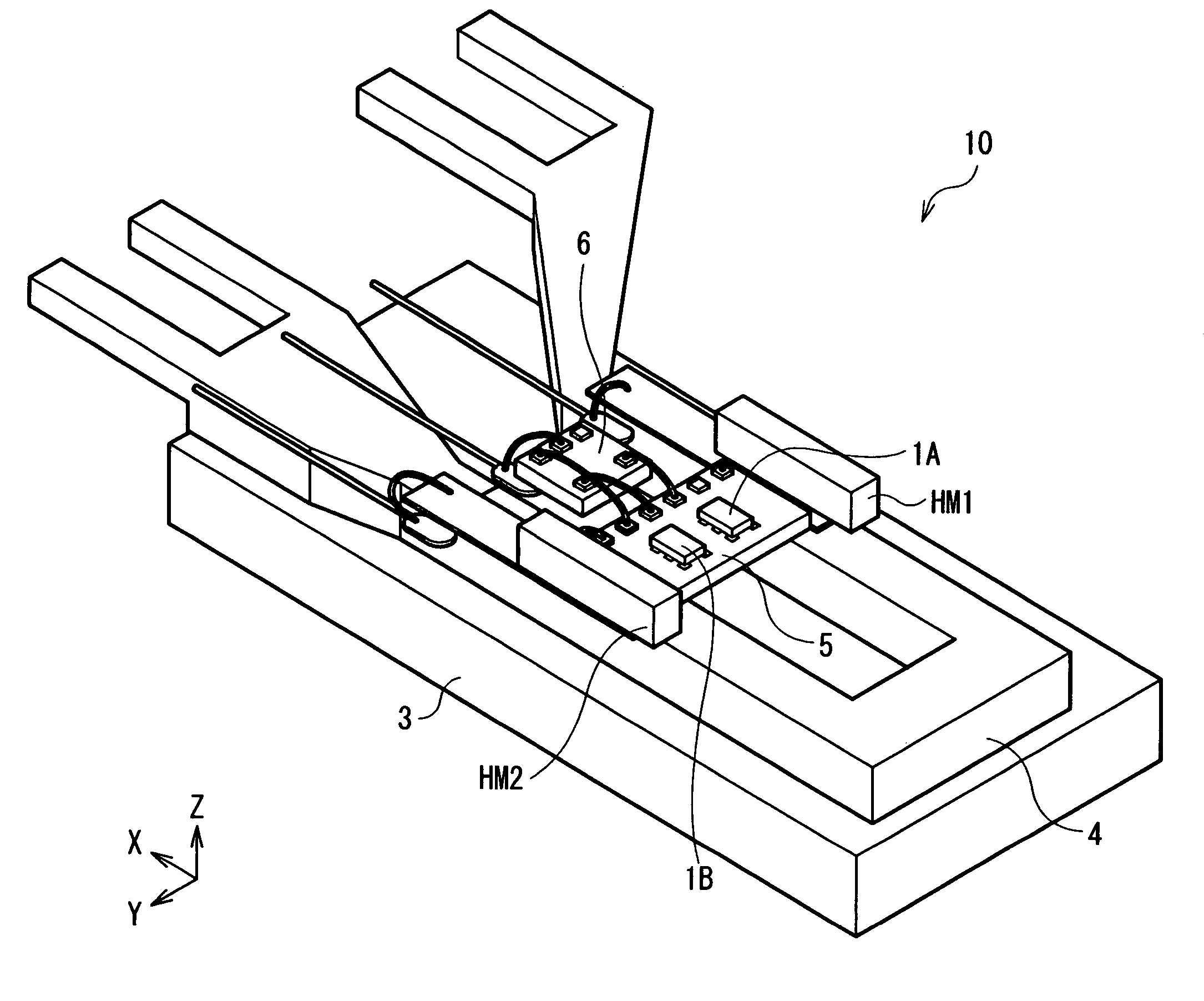
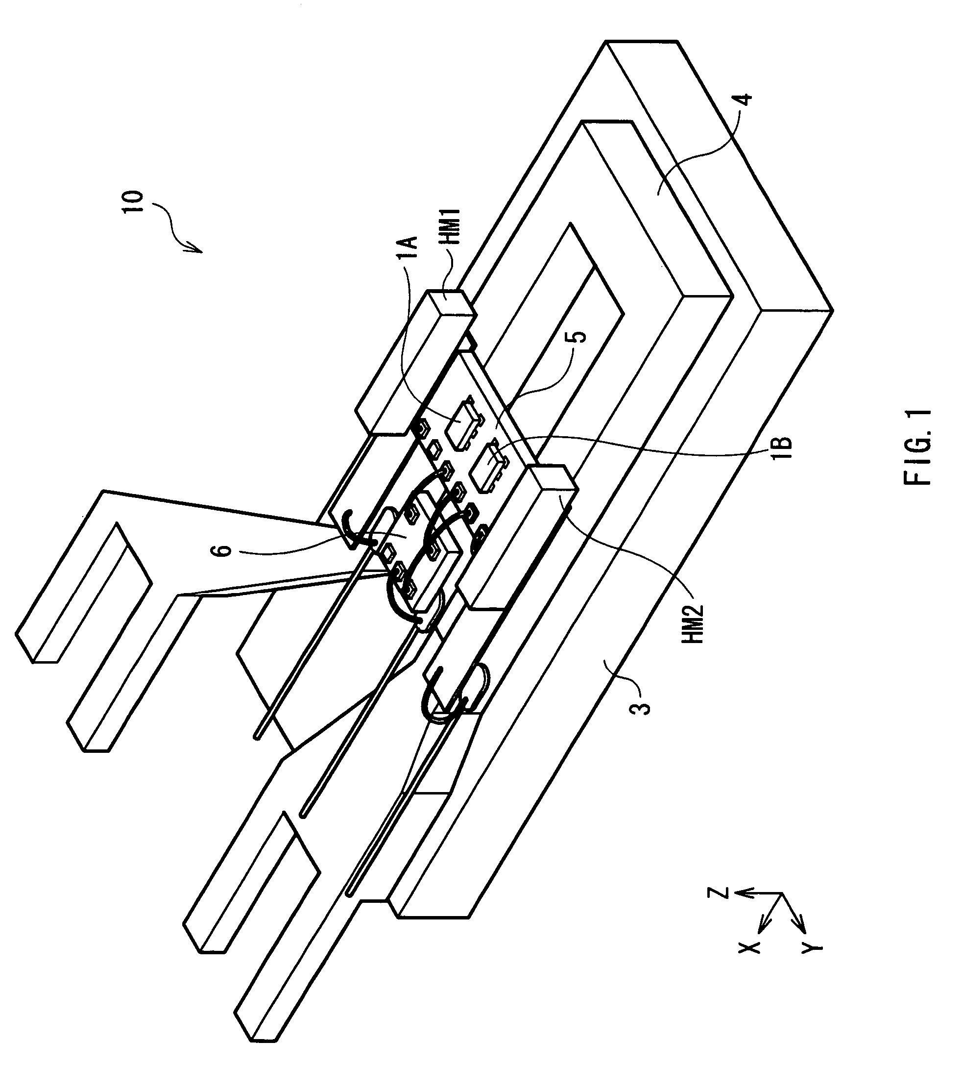
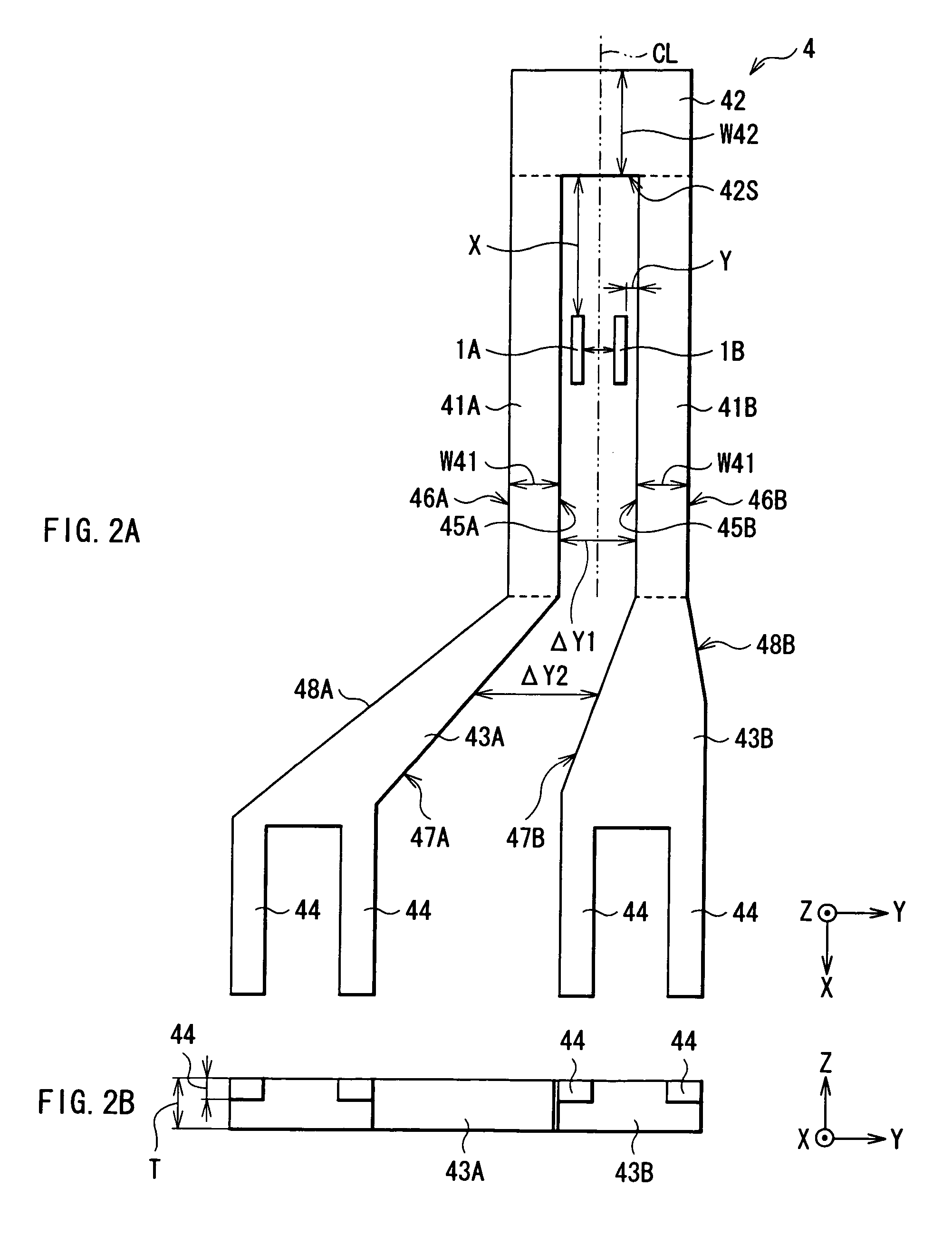
[0010]In the current sensor of an embodiment of the present invention, when a current to be detected flows from one of the pair of terminal portions into the other one of the pair of terminal portions in the conductor line having an almost U-shaped configuration as a whole, a current magnetic field is produced around each of the pair of parallel portions (as a central axis) and is applied to the magnetic sensor. At this time, since the pair of parallel portions have a same and uniform cross-sectional area each other, the current magnetic field makes a symmetric distribution on both sides of a hypothetical plane located at an equal distance from each of the pair of parallel portions so as to be stabilized. Further, since the pair of terminal portions extend to face with each other separated at a second distance being wider than the first distance therebetween, influence on the magnetic sensor given by the current magnetic field caused by a current flowing in the pair of terminal portions can be reduced. Moreover, since each of terminal portions has a larger cross-sectional area than that of each of the parallel portions, the Joule heat caused by the current to be detected is reduced and efficiently released to outside, and consequently an adverse influence on the magnetic sensor can be avoided.
[0013]In a current sensor of an embodiment of the present invention, it is preferred that the distance between the terminal portions becomes longer and cross-sectional area thereof becomes larger with increases in distance from the other ends of the parallel portions.
[0016]According to the current sensor of an embodiment of the present invention, since a conductor line is configured in such a way that one ends of a pair of parallel portions each having a same and uniform cross-sectional area, while extending in parallel with each other being separated at a first distance therebetween are connected by a connecting portion, and further, since the other end of each of the parallel portions are connected to a pair of terminal portions, while extending to face with each other separated at a second distance therebetween, a stable current magnetic field can be produced around each of the parallel portions as a central axis when a current to be detected is supplied to the conductor line, thus the current magnetic field can be applied to a magnetic sensor. In this case, influence which is exerted by the current magnetic fields produced in the pair of terminal portions on the magnetic sensor can be reduced. Moreover, since each of the terminal portions has a larger cross-sectional area than that of each of the parallel portions, an adverse influence exerted by the Joule heat caused by the passage of the current to be detected can be avoided. Thereby, there is an effect of being able to realize a miniaturization while capable of measuring the current to be detected with high precision and stability.

Problems solved by technology

However, in association with the miniaturization of dimension, there is a tendency that current sensors, even if using the foregoing GMR elements, are susceptible to magnetic noise from the surroundings and generation of heat etc.
Therefore, improvement in stability in a field of detection sensitivity and responsibility has been an issue.
Although several attempts have been made until now such as making the shape of the GMR elements a long and slender strip in order to increase shape anisotropy and so on, it is still difficult to say that the performance levels has been reached to a fully stabilized level.

Method used


Image

  • Current sensor
  • Current sensor
  • Current sensor

Examples


example

[0070]Next, an example of the present invention will be explained hereinbelow.

[0071]FIG. 10 represents a magnetic field distribution in the X-axis direction generated when currents to be detected Im of 15 A, 25 A, and 50 A are supplied to the conductor line 4, respectively in the current sensor of the above-mentioned embodiment. In FIG. 10, the horizontal axis represents a distance X with an origin of the side face 42S of the connecting portion 42, and the vertical axis represents a magnetic field Hx along the X-axis direction. As shown in FIG. 10, in the case where a current to be detected Im was 50 A or below, if the distance X was 5 mm or more, the magnetic field Hx was 0.5×10⁻⁴ T or less. In particular, if the distance X was set to 4 mm or more in the case where the current to be detected Im was 25 A, or if the distance X was set to 3 mm or more in the case where the current to be detected Im was 15 A, then the magnetic field Hx could be restrained to 0.5×10⁻⁴ T or less. This is...


PUM


Abstract

A current sensor includes a conductor line, and a magnetic sensor in which resistance value changes according to a current magnetic field produced by a current to be detected flowing through the conductor line. The conductor line includes: a pair of parallel portions each having a same and uniform cross-sectional area, while extending in parallel with each other separated at a first distance therebetween; a connecting portion connecting one end of one of the parallel portions and one end of the other of the parallel portions; and a pair of terminal portions each connected to the other end of each of the parallel portions, while extending to face with each other separated at a second distance therebetween, the second distance being wider than the first distance, the terminal portions each having a larger cross-sectional area than that of each of the parallel portions.

Description

BACKGROUND OF THE INVENTION[0001]1. Field of the Invention[0002]The present invention relates to a current sensor capable of precisely measuring current which flows through a conductor line.[0003]2. Description of the Related Art[0004]In order to accurately detect small control current flowing in a circuit of a control device, a method of connecting resistors in series in the circuit and measuring a voltage drop in the resistors is used in general. In this case, however, a load different from the control system is given, and there is a possibility that an adverse influence may be exerted on the control system. Consequently, a method of indirectly measuring a control current by detecting the gradient of a current magnetic field produced by the control current has been used. Specifically, an example includes a method of detecting a magnetic flux produced in a center portion of a toroidal core using a Hall device, the magnetic flux being produced by coiling a measurement line around th...

Claims


Application Information

Patent Timeline
Patent Type & Authority Patents(United States)
IPC IPC(8): G01R15/20G01R33/02
CPCG01R15/205G01R15/207H01L2224/4811H01L2224/48137
Inventor SHOJI, SHIGERU
Owner TDK CORPARATION
Why Eureka
Try Eureka