Magnetic sensor and current sensor

a current sensor and magnetic sensor technology, applied in the field can solve the problems of inability to achieve the sufficiently stable performance level of the challenge of improving detection sensitivity and responsiveness, and the increase of the noise of the outside environment of the magnetic sensor and current sensor, etc., to achieve the effect of high precision and stability, enhanced uniaxial anisotropy of the free layer, and favorable miniaturization

Active Publication Date: 2010-05-25
TDK CORPARATION
View PDF7 Cites 9 Cited by
  • Summary
  • Abstract
  • Description
  • Claims
  • Application Information

AI Technical Summary

Benefits of technology

[0007]The present invention has been achieved in consideration of such problems and it is desirable to provide a magnetic sensor capable of sensing a magnetic field to be detected with high precision and stability while realizing a compact configuration.
[0008]It is also desirable to provide a current sensor capable of sensing a current magnetic field generated by a current to be detected with high precision and stability while realizing a compact configuration.
[0011]In the magnetic sensor and the current sensor according to an embodiment of the invention, the bias applying means applies a bias magnetic field to the magnetoresistive elements, the bias magnetic field including an orthogonal component orthogonal to the magnetization direction of the free layer under no magnetic field and a parallel component parallel to the magnetization direction of the free layer under no magnetic field. Consequently, uniaxial anisotropy of the free layer is enhanced without using shape anisotropy.
[0016]The magnetic sensor of an embodiment of the invention has the bias applying means applying a bias magnetic field to the magnetoresistive element, and the bias magnetic field includes a parallel component parallel to the magnetization direction of the free layer under no magnetic field and an orthogonal component orthogonal to the free layer. Consequently, uniaxial anisotropy of the free layer can be enhanced without using shape anisotropy. Therefore, the magnetic field to be detected can be detected with high precision and stability irrespective of the shapes of the magnetoresistive elements, and the invention is favorable for miniaturization.
[0017]The current sensor of an embodiment of the invention has the bias applying means applying a bias magnetic field to first and second magnetoresistive elements disposed along a conductor so that resistance values change in directions opposite to each other in accordance with a current magnetic field generated by a current to be detected which flows through the conductor, and the bias magnetic field includes a parallel component parallel to the magnetization direction of the free layer under no magnetic field and an orthogonal component orthogonal to the parallel component. Consequently, uniaxial anisotropy of the free layer can be enhanced without using shape anisotropy. Further, the current to be detected is detected on the basis of the difference between a voltage drop which occurs in the first magnetoresistive element and a voltage drop which occurs in the second magnetoresistive element when constant currents of the same value are supplied. Thus, the current magnetic field generated by the current to be detected can be detected with high precision and stability while realizing a compact configuration.

Problems solved by technology

However, with miniaturization, even a magnetic sensor and a current sensor each using the GMR element are becoming more susceptible to noise from outside (unnecessary magnetic field or the like).
Accordingly, there is a challenge to improve stability in detection sensitivity and responsiveness.
Although some attempts such as increase in shape anisotropy by setting the shape of the GMR element to an elongated rectangular shape have been made, it cannot be said that the magnetic sensor and the current sensor have achieved the sufficiently stable performance level.

Method used


Image

  • Magnetic sensor and current sensor
  • Magnetic sensor and current sensor
  • Magnetic sensor and current sensor

Examples


example

[0068]Next, an example of the invention will be described hereinbelow.

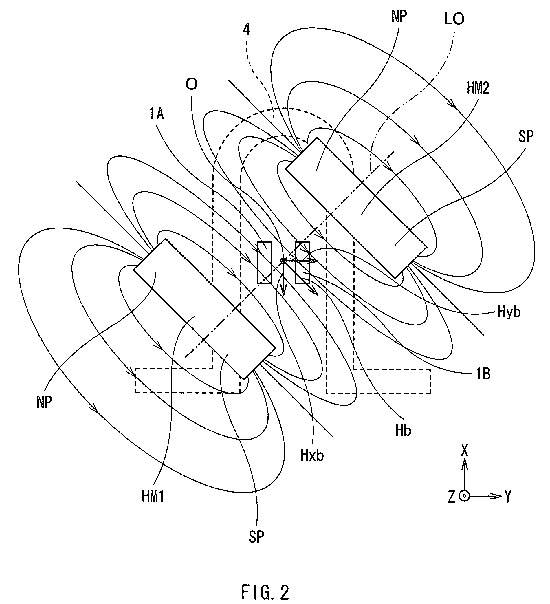
[0069]First, in the current sensor of the embodiment, a change in the resistance value R was measured in the case where each of a magnetic field Hx parallel to the magnetization direction of the pinned layer and a magnetic field Hy orthogonal to the magnetization direction of the pinned layer was applied to the magnetoresistive element. At that time, the bias magnetic field Hb including the parallel component Hxb and the orthogonal component Hyb was also applied. FIGS. 10 to 14 show the results. In this case, the positive / negative sign of the magnetic field Hx and that of the parallel component Hxb coincide with each other and, similarly, the positive / negative sign of the magnetic field Hy and that of the orthogonal component Hyb coincide with each other.

[0070]In each of FIGS. 10 to 14, the horizontal axis indicates the magnetic flux densities of the magnetic fields Hx and Hy and the vertical axis indicates the re...


PUM


Abstract

The present invention provides a current sensor capable of detecting a current magnetic field generated by a current to be detected with high precision and stability while realizing a compact configuration. The current sensor has: first and second magnetoresistive elements each including a pinned layer having a magnetization direction pinned in a predetermined direction, a free layer whose magnetization direction changes according to applied magnetic fields, and an intermediate layer sandwiched between the pinned layer and the free layer; and first and second permanent magnets for applying bias magnetic fields to the first and second magnetoresistive elements. The bias magnetic field has a parallel component parallel to a magnetization direction under no magnetic field and an orthogonal component orthogonal to the parallel component. Consequently, uniaxial anisotropy of the free layer can be enhanced without using shape anisotropy. Therefore, the current magnetic field to be detected can be detected with high precision and stability irrespective of the shapes of the magnetoresistive elements, and the invention is favorable for miniaturization.

Description

BACKGROUND OF THE INVENTION[0001]1. Field of the Invention[0002]The present invention relates to a magnetic sensor capable of sensing a change in magnetic field with high sensitivity and a current sensor capable of sensing a change in current flowing through a conductor with high sensitivity.[0003]2. Description of the Related Art[0004]Generally, to accurately detect weak control current flowing through a circuit in control equipment, a method of connecting resistors in series in the circuit and measuring a voltage drop in the resistors is used. In this case, however, a load different from that of a control system is applied and there is the possibility that an adverse influence is exerted on the control system. Consequently, a method of performing indirect measurement by detecting the gradient of a current magnetic field generated by the control current is used. As a concrete example, there is a method of winding a line to be measured around a toroidal core, supplying control curre...

Claims


Application Information

Patent Timeline
Patent Type & Authority Patents(United States)
IPC IPC(8): G01R33/02
CPCG01R33/09G01R15/205H01L2224/48091H01L2224/48137H01L2924/19107H01L2924/00014
Inventor SHOJI, SHIGERU
Owner TDK CORPARATION
Why Eureka
Try Eureka