Heatsink apparatus

a heat sink and apparatus technology, applied in lighting and heating apparatus, air heaters, semiconductor/solid-state device details, etc., can solve the problems of affecting the stability and operation efficiency of electronic components, unable to achieve the effect of quick and uniform dissipation, and limited heat dissipation area, etc., to achieve the effect of reducing the limitations or disadvantages of small heat dissipation area, poor heat dissipation performance, and too much space volum

Inactive Publication Date: 2008-12-09
INVENTEC CORP
View PDF12 Cites 5 Cited by
  • Summary
  • Abstract
  • Description
  • Claims
  • Application Information

AI Technical Summary

Benefits of technology

[0008]In view of the above problems, the present invention provides a heatsink apparatus, thereby eliminating the limitations or disadvantages of small heat-dissipation area of the heat conductive plate, poor heat-dissipation performance, and too much space volume occupied by the heatsink fin existing in the prior art.
[0009]The heatsink apparatus disclosed by the present invention is used to dissipate the heat generated by an electronic component in an electronic apparatus. The heatsink apparatus has a fan for generating an air flow and a heatsink fin. One end of the heatsink fin is adhered to the electronic component, and the other end is bended to form a curl portion. The curl portion is formed by a plurality of continuous inner surfaces. The inner surfaces have intervals in-between and are overlapped with one another. The air flow generated by the fan is conducted to at least one curl inner surface of the curl portion, and the winding axial direction of the curl portion is parallel to the air flow direction of the fan, so as to quickly dissipate the heat of the electronic component conducted to the curl portion.
[0010]The present invention is featured in that one end of the heatsink fin is wound to form a continuous bended curl portion, and the curl portion is correspondingly disposed at the vent of the air flow. The curl inner surfaces arranged with intervals in-between of the curl portion receives the convection air flow generated by the fan, so as to greatly increase the contact area between the heatsink fin and the convection air flow, and quickly dissipate the heat of the electronic component conducted to the curl portion.

Problems solved by technology

If the heat cannot be dissipated in time, the over-high temperature may seriously affect the stability and operating efficiency of the electronic components.
In the conventional heat-dissipation method, the effective heat-dissipation area of the heat conductive plate for dissipating heat by using the forced convection is the surface above the fan only, and the area of a direct air receiving surface of the heat conductive plate is equal to that of the fan vent at most, such that the heat-dissipation area is limited and cannot achieve the effects of quick and uniform dissipation.
However, the heat conductive plate with larger area may cause an increase of the heat-dissipation resistance of the heat conductive plate.
However, the problems of the increase of cost, big noise of fan, and complex arrangement of the entire system are generated.
In the conventional heat-dissipation method of FIG. 1B, the heat conductive plate and the heatsink fin must be connected by a bonding method, such as adhering or welding, so the manufacturing flow becomes more complex due to the step of bonding the heat conductive plate and the heatsink fin.
The heatsink fin can only provide additional heat-dissipating contact area, and cannot facilitate the flowing and conducting of the air flow, and the disposal of the heatsink fin occupies too much space.
In addition, as the heat conductive plate and the heatsink fin are not integrated into one piece, the junction therebetween is not completely sealed.
The contact area is quite limited, such that the total effect of heat-dissipation is poor.

Method used


Image

  • Heatsink apparatus
  • Heatsink apparatus
  • Heatsink apparatus

Examples


first embodiment

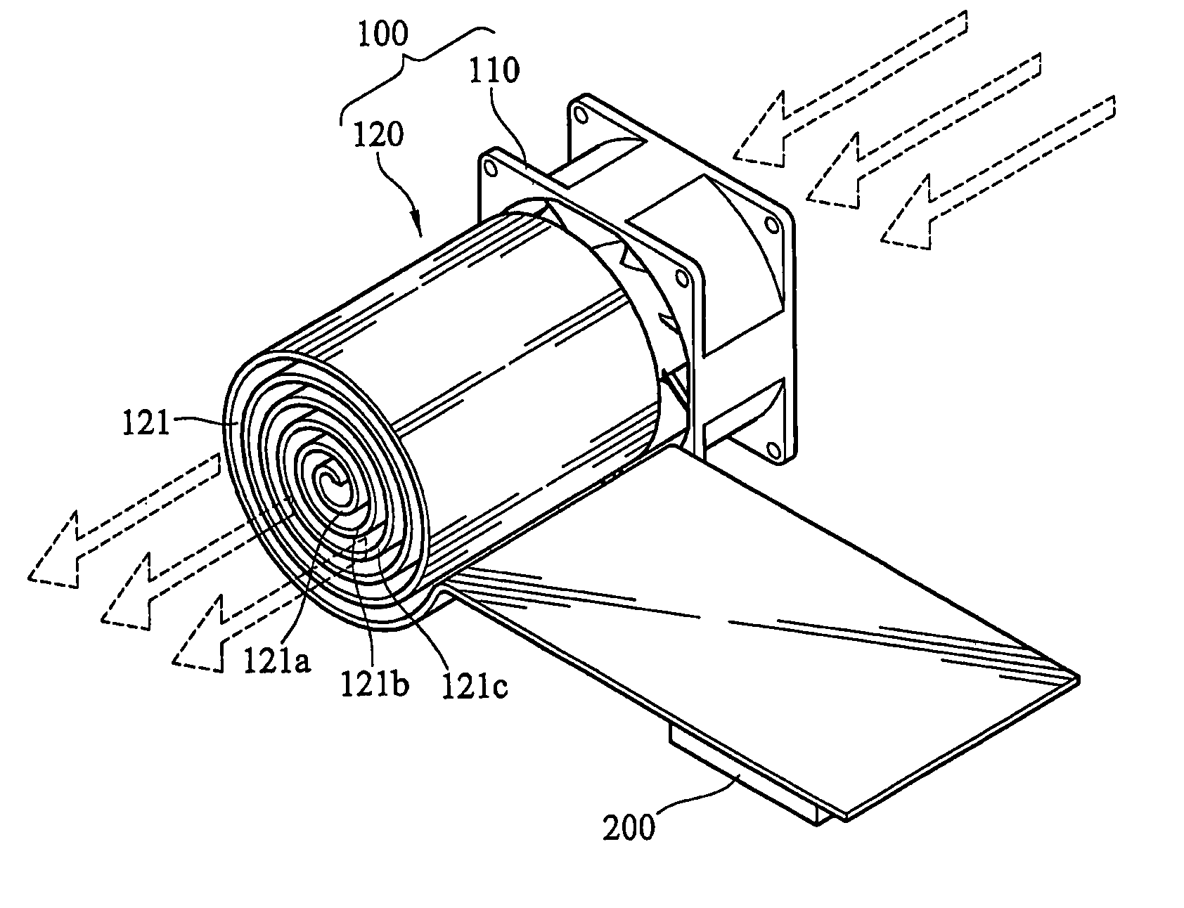
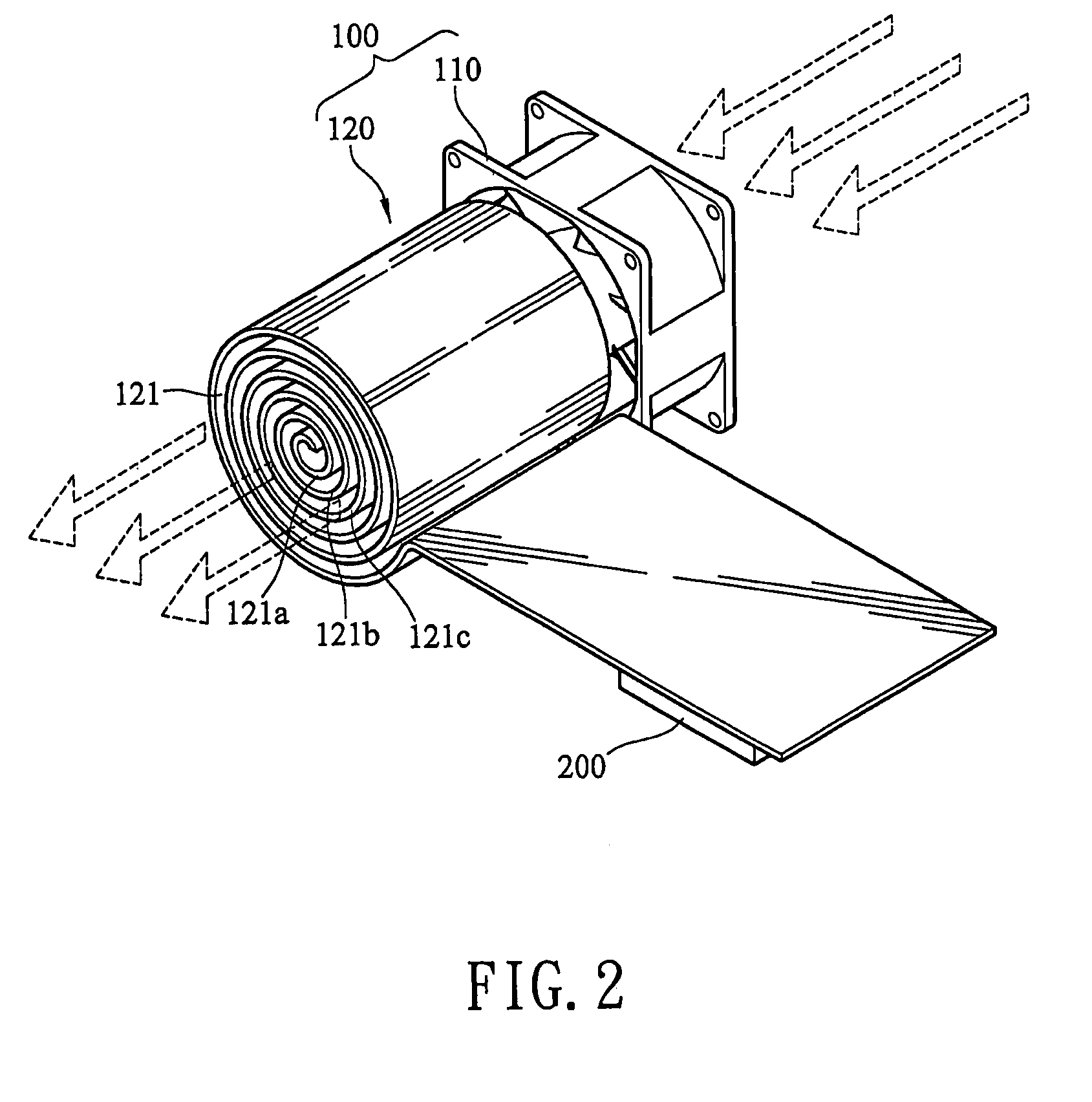
[0024]FIG. 2 is a schematic isometric view of the present invention. As shown in the figure, the heatsink apparatus 100 of the present invention is used to dissipate the heat generated by the electronic component 200 in the electronic apparatus, and the electronic component 200, such as a chip and a processor, generates high heat energy during operating. The heatsink apparatus 100 disclosed by the present invention includes a fan 110 and a heatsink fin 120. The fan 110 is used to generate a convection air flow and dissipate the heat by forced convection. One end of the heatsink fin 120 is adhered to a surface of the electronic component 200, and the other end is bended to form a curl portion 121. Therefore, the heat generated by the electronic component 200 is conducted to the curl portion 121 of the other end via one end adhered to the heatsink fin 120. The position where the curl portion 121 is installed corresponds to the vent of the fan 110. The convection air flow blown by the ...

second embodiment

[0026]FIG. 3 is a schematic isometric view of the present invention. The fan 110 disclosed by the present invention may be a side flow fan, and the vent is disposed at the side position. The air flow firstly passes through blades of the fan, and then is blown out through the vent perpendicular to the blade. The curl portion 121 is disposed with its winding axial direction parallel to the side vent of the side flow fan 110, such that the curl inner surfaces 121a, 121b, and 121c in the curl portion 121 can completely receive the air flow generated by the fan 110. The air flow passes through the hollow portion of the curl portion 121, and contacts with the heatsink surface of the curl portion 121 to the maximum extent, so as to quickly dissipate the heat of the electronic component 200 conducted to the curl portion 121.

[0027]Referring to FIG. 4, according to the practical requirements on the circuit board configuration in the electronic apparatus, the curl portion 121 of the present in...


PUM


Abstract

A heatsink apparatus for dissipating heat generated by electronic parts is provided. The heatsink apparatus includes a fan and a heatsink fin. One end of the heatsink fin is adhered to an electronic component, the other end forms a curl portion, and a curl inner surface receives an air flow generated by the fan, so as to quickly dissipate the heat energy of the electronic component.

Description

BACKGROUND OF THE INVENTION[0001]1. Field of Invention[0002]The present invention relates to a heatsink apparatus. More particularly, the present invention relates to a heatsink apparatus with a large heat-dissipation area.[0003]2. Related Art[0004]Along with the quick development and expansion of the application scope of high-tech industry, such as electronic information, portable computers have been increasingly popularized. The operating speed of electronic components, such as central processing units (CPU), hard disk drives (HDD) inside the portable computer apparatuses, increasingly becomes high, and the electronic components are miniaturized, so the heat-generating volume of a unit area is increased. If the heat cannot be dissipated in time, the over-high temperature may seriously affect the stability and operating efficiency of the electronic components.[0005]In order to effectively dissipate the heat generated by the electronic components, heatsink modules are installed in t...

Claims


Application Information

Patent Timeline
Patent Type & Authority Patents(United States)
IPC IPC(8): H05K7/20F28F7/00H01L23/34
CPCH01L23/467H01L2924/0002H01L2924/00
Inventor WANG, FENG-KUYANG, CHIH-KAI
Owner INVENTEC CORP
Why Eureka
Try Eureka