
Electric toothbrush

a toothbrush and electric technology, applied in the field of electric toothbrushes, can solve the problems of toothbrush and flosser, as described, not providing elliptical rotation of the head or means of spacing the toothbrush away from the teeth

Inactive Publication Date: 2008-12-16
FILSOUF EHSAN
View PDF8 Cites 14 Cited by
  • Summary
  • Abstract
  • Description
  • Claims
  • Application Information

AI Technical Summary

Benefits of technology

"The present invention is an electric toothbrush that has a reversible, elliptical brushing motion. This allows the user to brush from the gums to the tips of the teeth, regardless of which hand they are using or whether they are brushing the upper or lower teeth. The brush bristles are split and extend on either side of a soft spacer pad which may be rested against the teeth. The spacer maintains the bristles at a given distance away from the teeth, such that they brush against the teeth on the near, brushing stroke, portion of an elliptical orbit about an axis of the shaft while pulling away from the teeth on the far, recovery, portion of the elliptical orbit. An automatic, position sensitive switch allows the user to change the brushing direction of the bristles by a simple change of the angle of the wrist in order to change from brushing the left or right or the front or the back of the teeth. A three position switch on the handle allows the user to selectively reverse the motor for brushing the upper teeth or the lower teeth. The invention provides an electric toothbrush that can brush both the upper and lower teeth, with the bristles stroking away from the gums, as recommended by dental professionals. It also allows the user to change the direction of the bristle stroke by a simple change of wrist position. The invention is relatively light weight, durable, and economical to purchase and operate."

Problems solved by technology

Most of the brushes which do provide a rotary motion, and thus only brush away from the gum, as advised by dental professionals, present other problems.
The toothbrush and flosser, as described do not provide elliptical rotation of the head or means of spacing the brushes away from the teeth.

Method used


Image

  • Electric toothbrush
  • Electric toothbrush
  • Electric toothbrush

Examples


Embodiment Construction

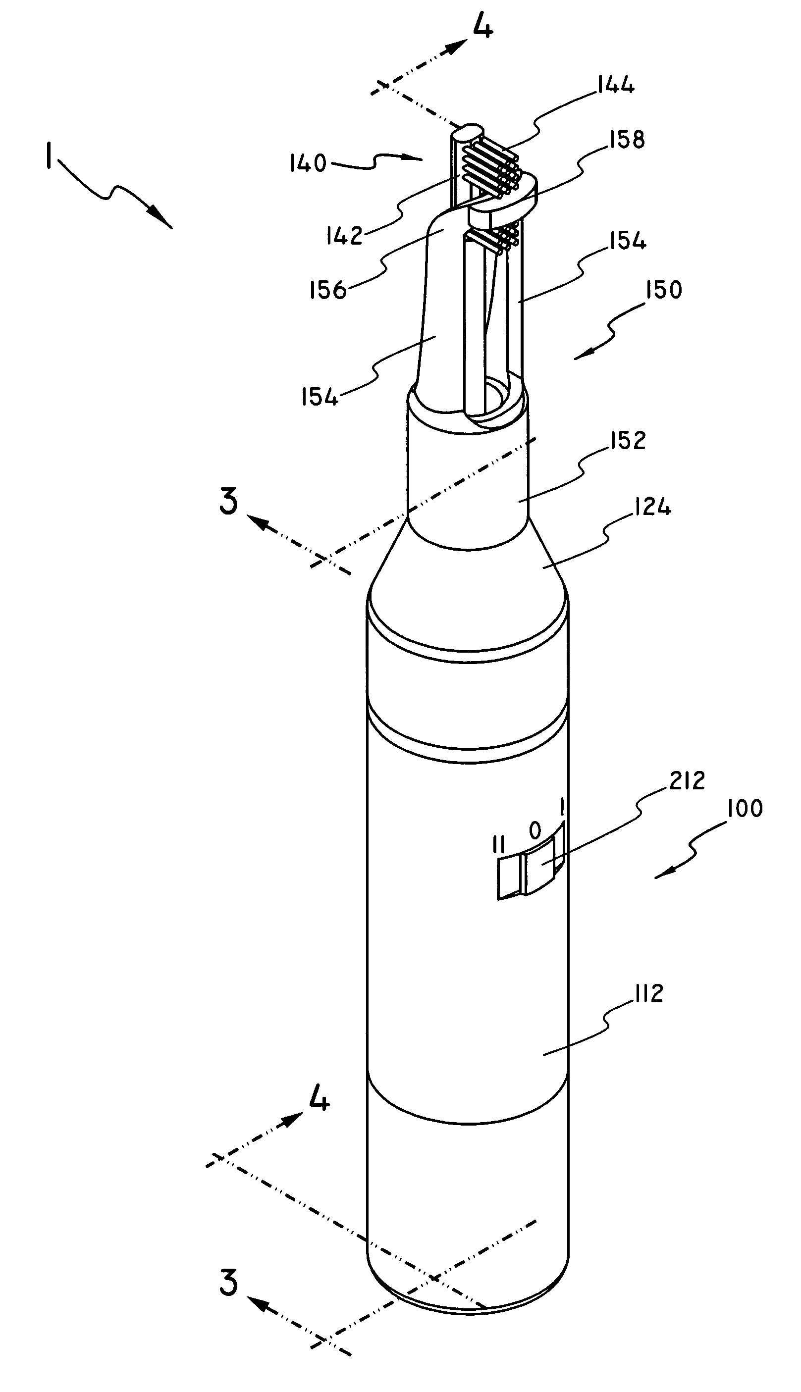
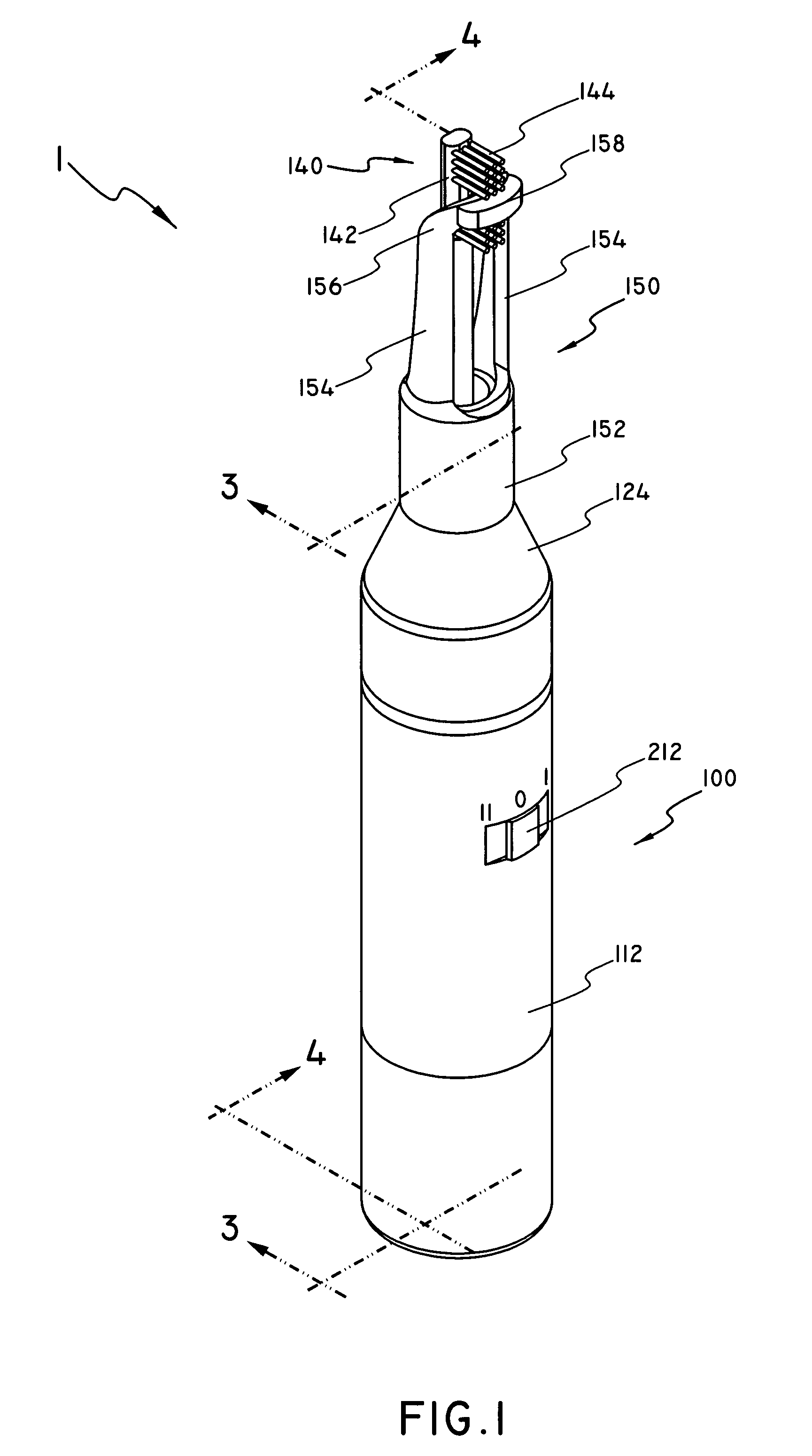
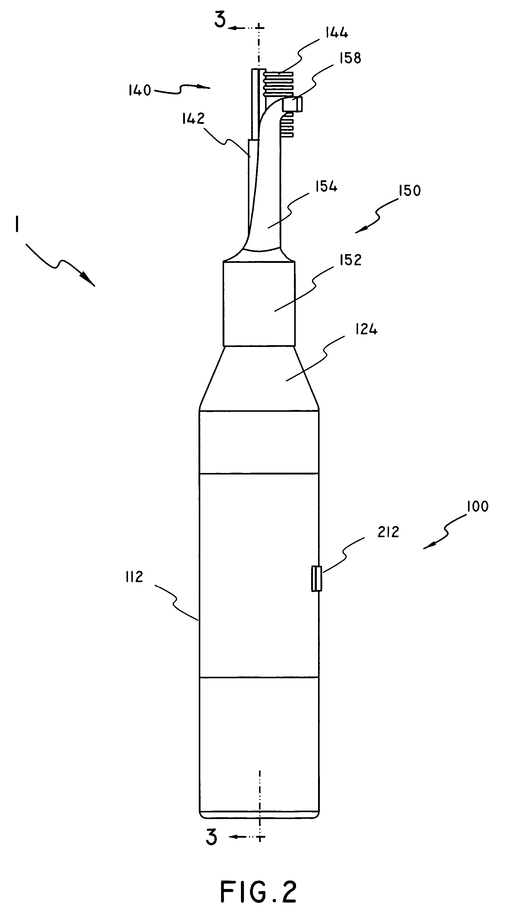
[0036]The toothbrush 1, generally presented at FIGS. 1 and 2, includes a handle 100 and a brush head 140. Handle 100 is further composed of a body housing 112 and shoulder housing 124, while brush head 140 is further composed of brush shaft 142 and bristles 144. A switch 212 controlling the a motor 200 (FIG. 5) located within the body housing 112 is located on the body housing 112. The body housing 112 is substantially cylindrical in shape, having a closed lower end and an open upper end. It would be evident to one of ordinary skill in the art, however, that the body housing 112 may take any one of a variety of other shapes without departing from the spirit of the invention. The shoulder housing 124 is substantially frustoconical in shape having a larger, open lower end adapted to mate with the open upper end of the body housing 112 and a substantially closed upper end with an aperture centered therein allowing the passage of a brush drive shaft (to be detailed herein below).

[0037]S...


PUM


Abstract

An electric toothbrush in which the brushing head moves in an elliptical motion such that, on the brushing stroke, the bristles are proximate the teeth, and in the recovery portion of the cycle the bristles are pulled away from the teeth. A position sensitive switch automatically switches from a forward to a reverse operation of the electric motor, depending on the positioning of the toothbrush in a user's hand, allowing the user to brush both the upper and lower teeth using a stroke carrying the bristles from the gum line to the ends of the teeth, as is recommended by dental professionals, without having to move the toothbrush from hand to hand or manually move the switch from the forward to the reverse positions. A bridge pad engages the face of the teeth, maintaining a proper distance between the teeth and bristles during the elliptical rotation of the brush head.

Description

BACKGROUND OF THE INVENTION[0001]1. Field of the Invention[0002]The present invention relates to electric toothbrushes. More particularly, the invention comprises an electric toothbrush having a reversible, elliptical rotation pattern of the brushing head, allowing strokes which brush away from the gums, regardless of which hand the user uses or whether he is brushing the upper or lower teeth.[0003]2. Description of the Prior Art[0004]Electric toothbrushes are well known in the art. Most electric toothbrushes, however, provide only an up and down motion, thereby brushing into the gum on half of the brush strokes. Most of the brushes which do provide a rotary motion, and thus only brush away from the gum, as advised by dental professionals, present other problems.[0005]U.S. Pat. No. 5,974,296, issued to Tit Shing Wong on Aug. 18, 1998, discloses an ELECTRIC TOOTHBRUSH, having a reversible, rotary brush head activated by a switch at the brush head, which is placed inside the mouth. By...

Claims


Application Information

Patent Timeline
Patent Type & Authority Patents(United States)
IPC IPC(8): A61C17/22
CPCA61C17/3472A61C17/40
Inventor FILSOUF, EHSAN
Owner FILSOUF EHSAN
Learn More