Adjustable hold-down for sickle guards

a technology of sickle guards and clamping plates, which is applied in the field of clamping plates, can solve the problems of reducing cutting efficiency, improper blade clearance operation of mowers, and wide use, and achieves the effect of reducing transverse cross-sectional, easy and reliably adjusted

Inactive Publication Date: 2008-12-16
BLUE LEAF I P
View PDF21 Cites 13 Cited by
  • Summary
  • Abstract
  • Description
  • Claims
  • Application Information

AI Technical Summary

Benefits of technology

[0009]Accordingly, it is an object of the present invention is to provide a sickle bar hold-down with a novel mechanism for adjusting the spatial relationship between the hold-down and the sickle knife sections.
[0011]It is another object of the instant invention to provide a forged sickle bar hold-down that has an elongated finger-like body portion with a knife section facing surface and a reduced transverse cross-sectional area at a strategic location that allows selective flexing of the finger-like body portion adequate to adjust the spatial relationship between the knife section facing surface and the sickle knife sections.
[0013]It is yet another object of this invention to provide an improved sickle bar hold-down that is durable in construction, inexpensive to manufacture, carefree of maintenance, facile in assemblage, and simple and effective in use.

Problems solved by technology

Heretofore known hold-down mechanisms, such as those shown in U.S. Pat. Nos. 3,490,215, 3,577,716, 4,012,891, 4,894,979 and 6,305,154 are widely used, but have not been entirely satisfactory.
The difficulty of adjusting such mechanisms often results in mowers being operated with improper knife clearance.
Too much clearance allows crop material to force the knife section away from the cutting edges of the guards, greatly reducing cutting efficiency.
Too small a clearance results in drag on the sickle bar assembly and a resultant increase in wear rate and power requirements.
This method is time consuming and inconvenient, and usually requires removal of the sickle bar so that the adjustment must be checked by means of a gauge rather than by direct measurement with the knives in place.
Both the conventional hold-down clip and the screw adjusted versions are typically placed between guards where they suffer additional dual disadvantages—first, of being located so as to snag crop material divided and deflected into this area by the guards, and second, of having only an indirect effect in controlling knife clearances in that they are not directly above the guard ledger surfaces.
This type of hold-down clip is in constant contact with the knife sections and the drag between them increases wear rate and the power required to operate the mowing apparatus.
Typically, screw adjustment is provided to raise or lower the forward part of the clip, but before the screw adjustment can be made, the screw fastener must be loosened to permit pivoting of the hold-down clip, consequently loosening the guards and upsetting adjustment of the wear plates between the sickle bar assembly and the frame member.

Method used


Image

  • Adjustable hold-down for sickle guards
  • Adjustable hold-down for sickle guards
  • Adjustable hold-down for sickle guards

Examples


Embodiment Construction

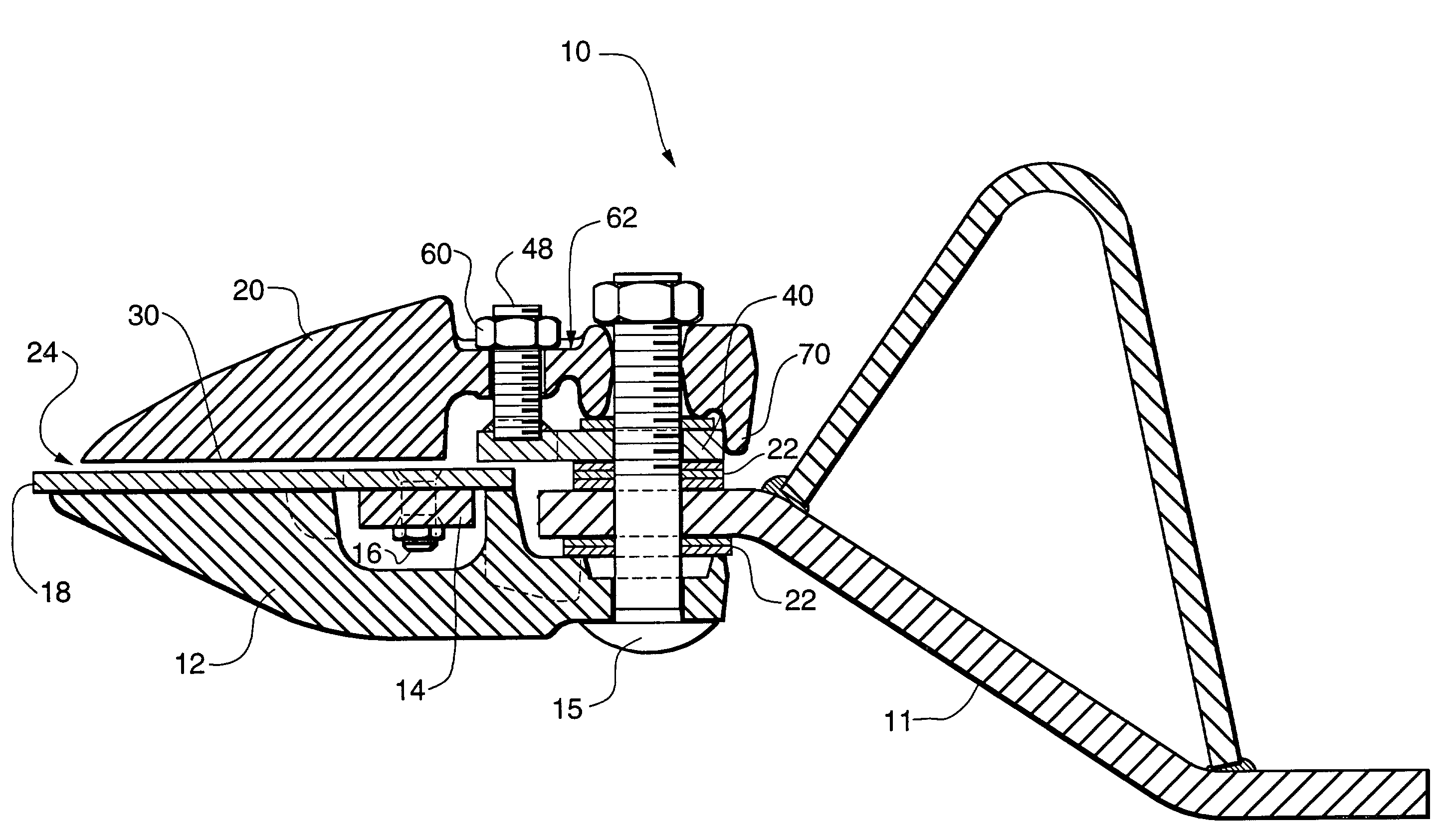
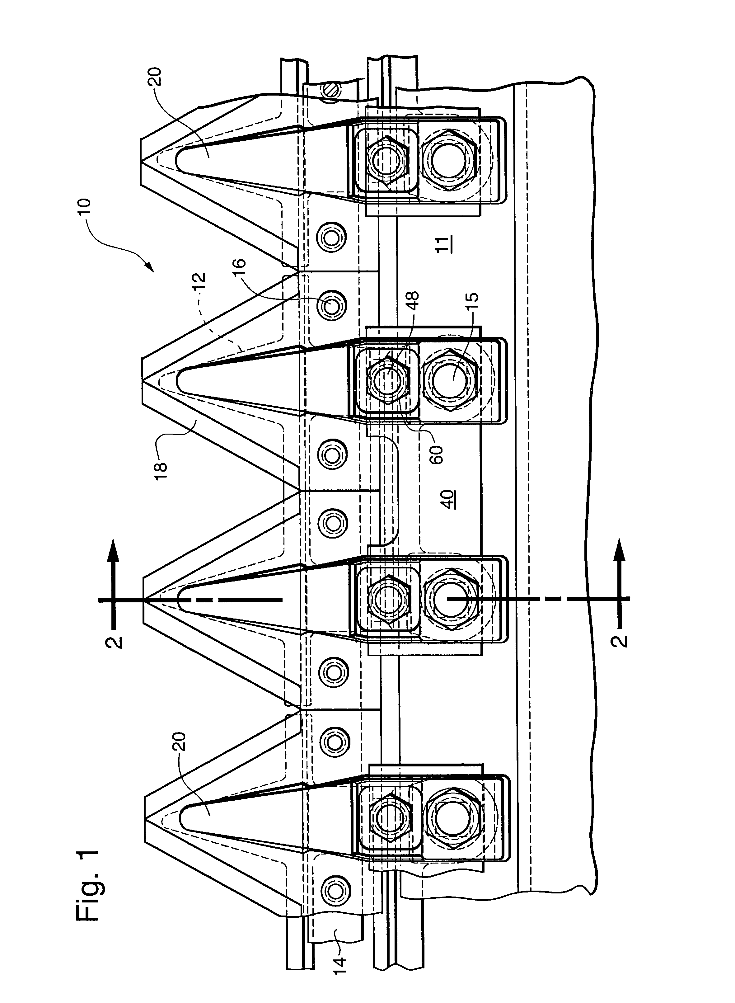
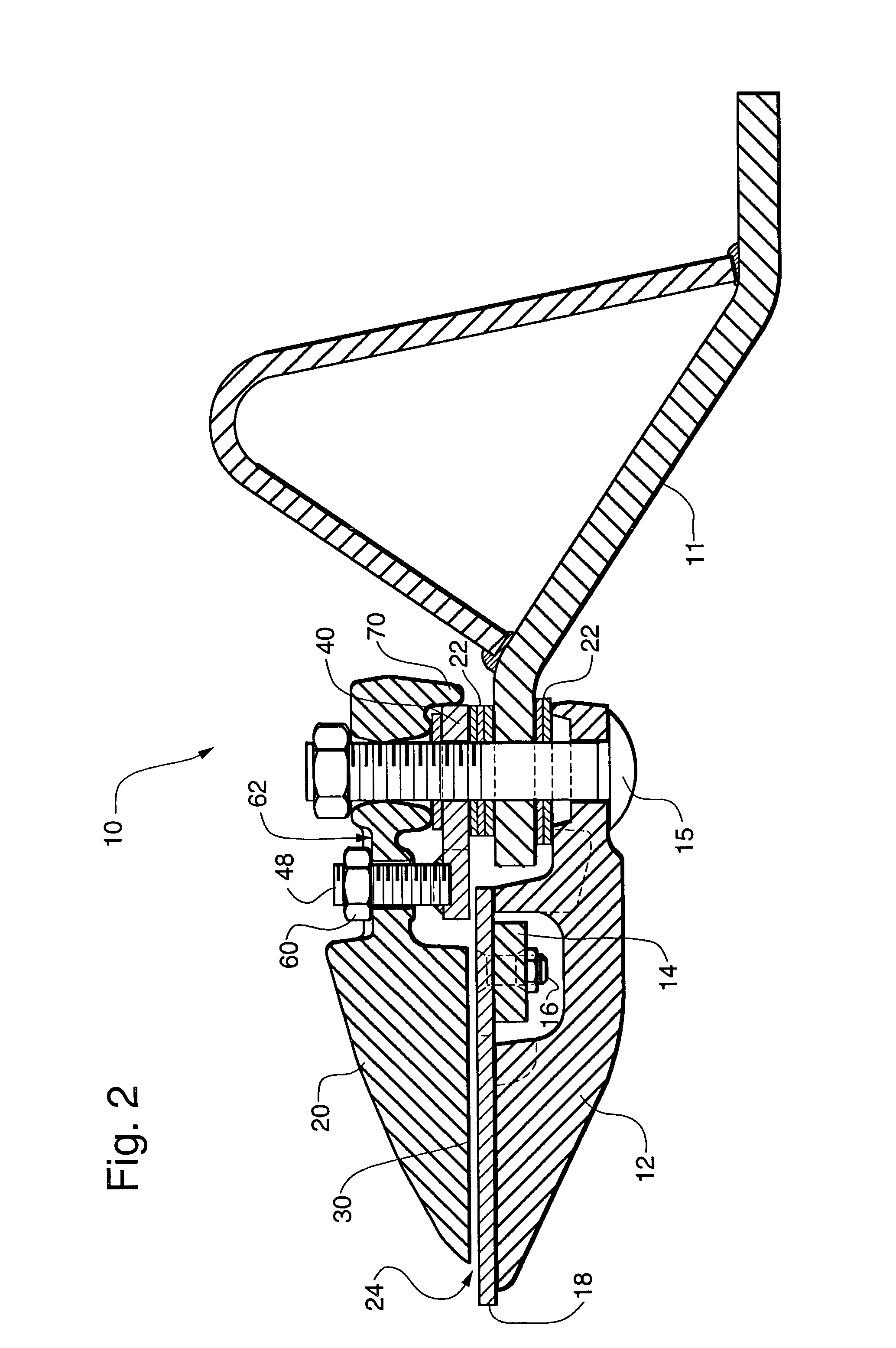
[0026]The harvester or other machine with which the hold-down of the present invention is utilized has a crop cutting mechanism, most commonly referred to as a reciprocating sickle-type “cutterbar”10 that normally extends horizontally across the path of forward travel of the harvester. The cutterbar 10 is typically affixed to the forward lower portion of a frame structure or a fairly rigid metallic floor member 11 so as to present the cutterbar at the initial crop-engaging portion of the machine. A plurality of sickle guards 12, shown in phantom in FIG. 1, are positioned regularly across the bottom of the cutterbar. An elongate knife-back 14 also extends across the cutterbar and has removably affixed thereto by bolts 16, a plurality of knife sections 18. The knife sections 18 are reciprocated lengthwise (by means, not shown, at one or both ends depending upon whether it is a single or double sickle bar cutterhead) so that the cutting edges on the knives register with the generally m...


PUM


Abstract

A forged sickle bar hold-down formed with a reduced transverse cross-sectional area and a first hole therethrough positioned toward the rear end of the hold-down is disclosed. The hold-down includes a second hole therethrough positioned between the reduced cross-sectional area and the first hole. In use, an attachment bolt is positioned through the first hole and a support bar and rigidly affixed thereto. A threaded adjustment bolt is inserted through the second hole and the support bar to selectively draw down on that portion of the hold-down forward of the reduced transverse cross-sectional area and thereby flex the forward portion of the hold-down which includes an elongated finger-like body portion with a knife section facing area.

Description

CROSS-REFERENCE TO RELATED APPLICATIONS[0001]The invention is this application is related to those disclosed and claimed in U.S. application Ser. Nos. 10 / 319,291, 10 / 319,353 and 10 / 319,355 entitled,respectively, “Mechanism for Preventing Misalignment of Hold-Downs”, “Sickle Cutterbar Assembly”, and “Stud Plate for Sickle Bar Hold-Down”. All of these applications were filed on the same date as the instant application, and all have the same inventors.BACKGROUND OF THE INVENTION[0002]The present invention relates generally to a mowing apparatus of the reciprocating sickle type and more particularly to a hold-down with improved adjustment characteristics.[0003]The general mode of operation of reciprocating sickle bar mowing apparatus is well known, as is the importance of keeping the sickle bar knife sections substantially parallel to the ledger surface on the guards, and maintaining the proper clearance between them for good shearing action. Some form of hold-down clip or plate extendi...

Claims


Application Information

Patent Timeline
IPC IPC(8): A01D34/18A01D34/17
CPCA01D34/17
Inventor BLAKESLEE, EDWARD A.GLASS, EMMETT F.
Owner BLUE LEAF I P
Why Eureka
Try Eureka