Sun tracker for solar panels

a solar panel and tracker technology, applied in the field of solar panels, can solve the problems of high power required, lack of spare power in recreation vehicles, and inclusion of such panels

Inactive Publication Date: 2008-12-16
AARON JACK
View PDF6 Cites 11 Cited by
  • Summary
  • Abstract
  • Description
  • Claims
  • Application Information

AI Technical Summary

Problems solved by technology

But few include such panels equipped to follow the position of the sun.
The primary reason for this is the high power required for operation of a sun tracker and the lack of spare power in recreation vehicles.

Method used


Image

  • Sun tracker for solar panels
  • Sun tracker for solar panels
  • Sun tracker for solar panels

Examples


Embodiment Construction

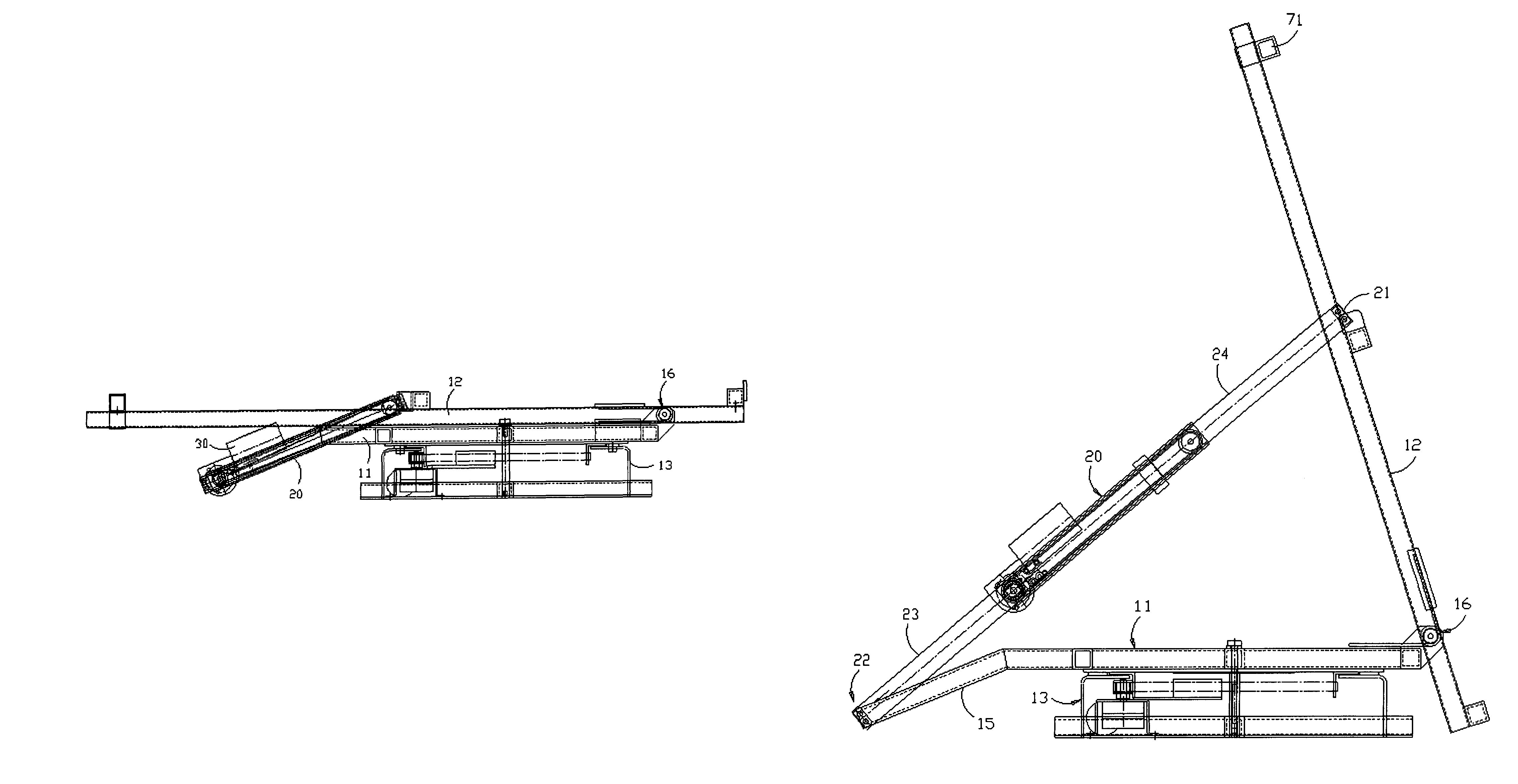
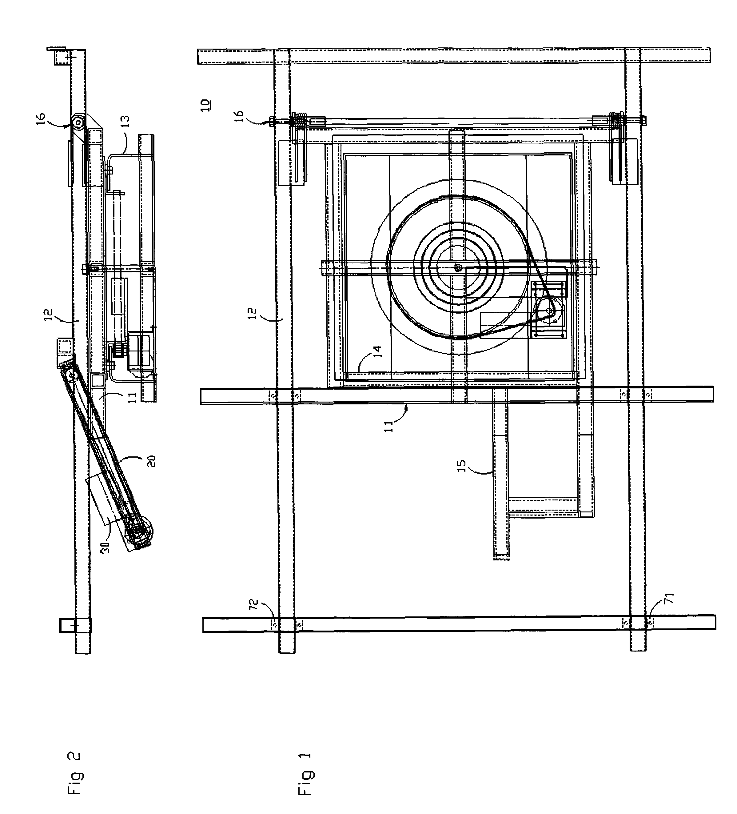
[0008]FIG. 1 is a schematic top view of a solar panel assembly 10 in accordance with the principles of this invention. The assembly comprises a base member 11 and a movable member 12 hinged to the base member and operative to move about the hinge between a collapsed position and an elevated position controllably in a manner to track the position of the sun.

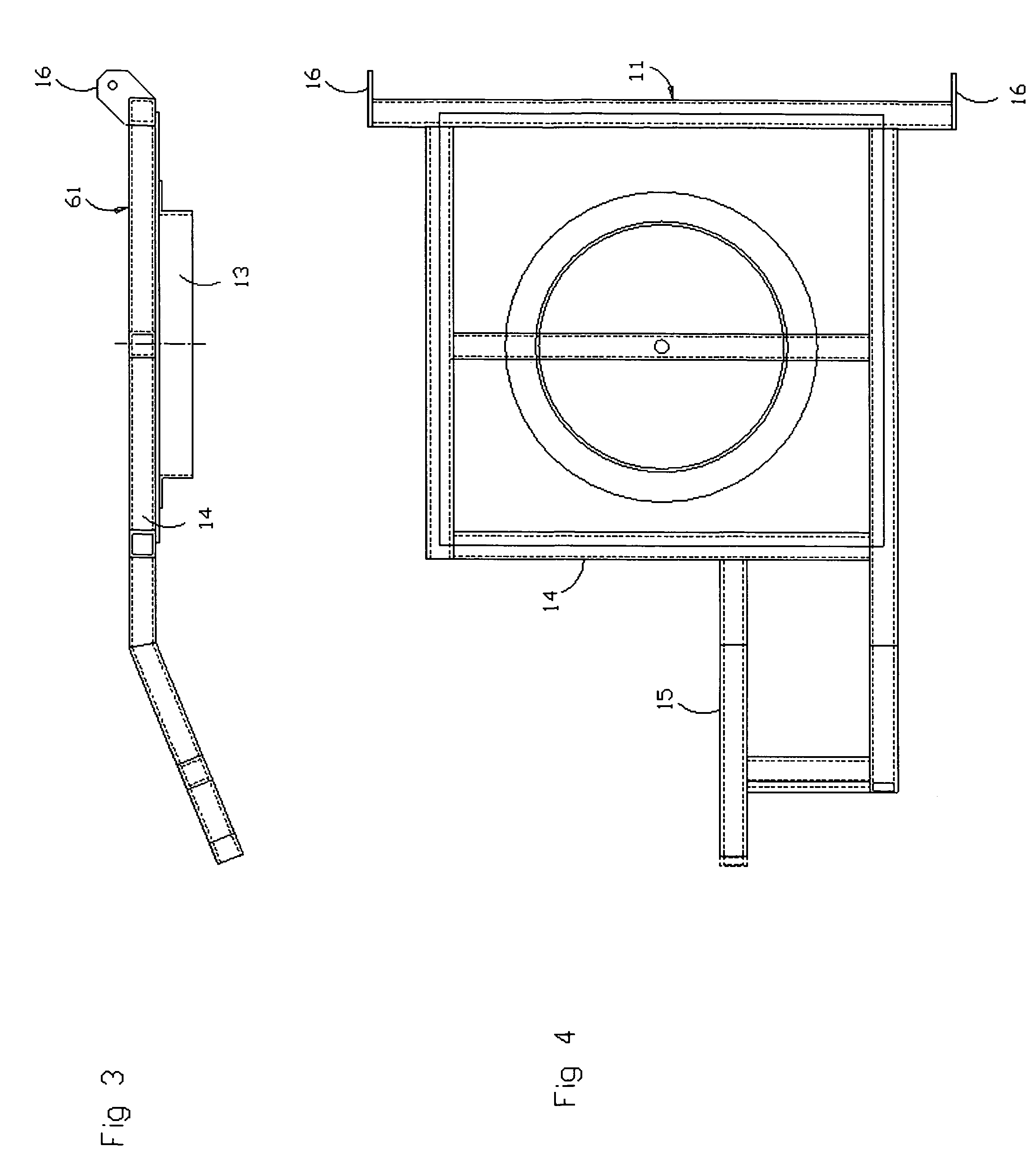
[0009]FIG. 2 is a schematic side view of the assembly of FIG. 1 showing the movable member in a collapsed position with respect to the base member. FIG. 3 is a schematic side view of the base member alone and FIG. 4 is a schematic top view of the base member alone. FIG. 5 is a schematic side view of the assembly of FIG. 1 showing the movable member in an elevated position.

[0010]Base member 11 illustratively fits on a pedestal 13 shown in FIG. 3 and (enlarged) in FIG. 2. The pedestal is for attachment to the roof of a recreational vehicle and thus anchors the base member into a fixed position determined by the position of the vehic...


PUM


Abstract

The elevation of a solar panel to follow the course of the sun is achieved in a manner to require relatively little power. The elevation mechanism utilizes a system of wires and pulleys which cooperate with springs which are compressed when the panel is in the collapsed position. The springs operate to overcome inertia when panel elevation first commences. The wire and pulley system operates to extend in opposite directions a pair of arms, one connected to the panel base member, the other connected to the top of the panel pivoting member.

Description

CROSS REFERENCE TO RELATED APPLICATIONS[0001]The present application claims the benefit of priority of provisional application Ser. No. 60 / 709,415 filed Aug. 18, 2005 for Jack Aaron.FIELD OF THE INVENTION[0002]This invention relates to a solar panel including apparatus for adjusting the orientation of the panel on a mobile platform such as a recreational vehicle, and more particularly to such apparatus which requires relatively little energy.BACKGROUND OF THE INVENTION[0003]Recreational vehicles equipped with solar panels are well known. But few include such panels equipped to follow the position of the sun. The primary reason for this is the high power required for operation of a sun tracker and the lack of spare power in recreation vehicles.BRIEF DESCRIPTION OF THE INVENTION[0004]In accordance with the principles of this invention a system of pulleys is operative in cooperation with a spring system to provide for a low power operation for moving a pair of rods in opposite directio...

Claims


Application Information

Patent Timeline
Patent Type & Authority Patents(United States)
IPC IPC(8): F24J2/38F24S50/20
CPCF24J2/541H02S30/20H02S20/00F24J2002/5458Y02E10/50Y02E10/47H02S20/32F24S2030/133F24S30/425
Inventor AARON, JACK
Owner AARON JACK
Why Eureka
Try Eureka