
Electrical grounding strip

a technology of electrical grounding and electrical wires, which is applied in the direction of electrical apparatus casings/cabinets/drawers, coupling device connections, lighting conductor installation, etc., can solve the problems of difficult rapid deployment system use, inability to reuse rods, and requiring substantial crew effort and tim

Inactive Publication Date: 2008-12-16
LOCKHEED MARTIN CORP
View PDF8 Cites 7 Cited by
  • Summary
  • Abstract
  • Description
  • Claims
  • Application Information

AI Technical Summary

Benefits of technology

The patent describes a way to ground electrical equipment using a special strip made up of two links. Each link has a part that lies in a plane and has a conductive spike that sticks out from the plane. The spikes make contact with a flexible conductor that grounds the equipment. The method involves placing the strip in a way that the spikes are pointing towards a grounding surface and connecting them to the equipment. This helps to ensure a good electrical connection and reduces the risk of electrical arcing. The technical effect of this invention is to provide a reliable and safe way to ground electrical equipment.

Problems solved by technology

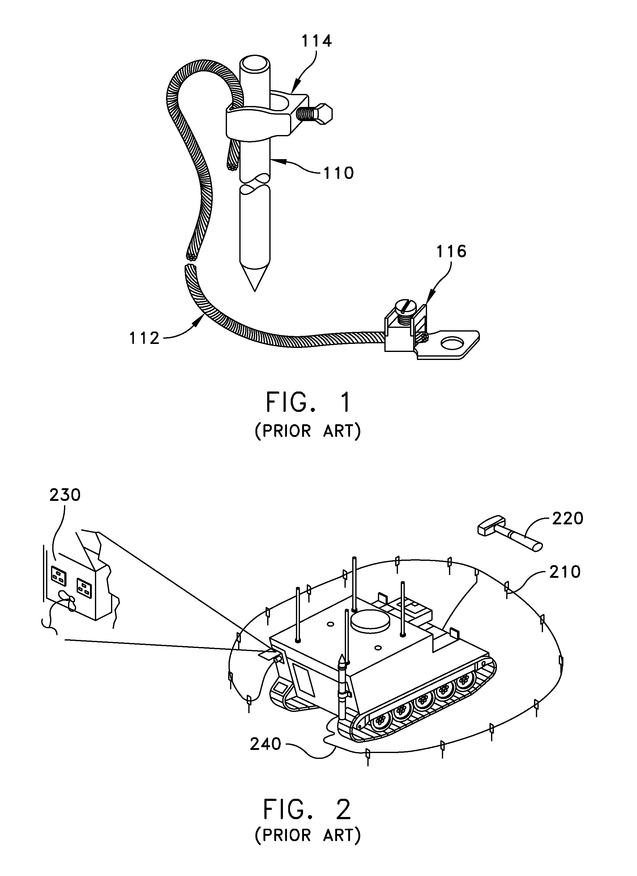
One shortcoming of this method is that it is very difficult to use for rapidly deploying systems because it requires considerable crew effort and time to install the grounding rod.
Another shortcoming is that such a rod is not re-usable because considerable time and energy would be required to completely pull out the grounding rod.
This requires substantial crew effort and time to drive each of the grounding stakes into the ground around the deployed system.
This requires considerable crew effort and time because each stake has to be individually pulled out of the ground.

Method used


Image

  • Electrical grounding strip
  • Electrical grounding strip
  • Electrical grounding strip

Examples


Embodiment Construction

[0015]It is to be understood that the figures and descriptions of the present invention have been simplified to illustrate elements that are relevant for a clear understanding of the present invention, while eliminating, for purposes of clarity, many other elements found in typical grounding methods and systems. However, because such elements are well known in the art, and because they do not facilitate a better understanding of the present invention, a discussion of such elements is not provided herein. The disclosure herein is directed to all such variations and modifications known to those skilled in the art.

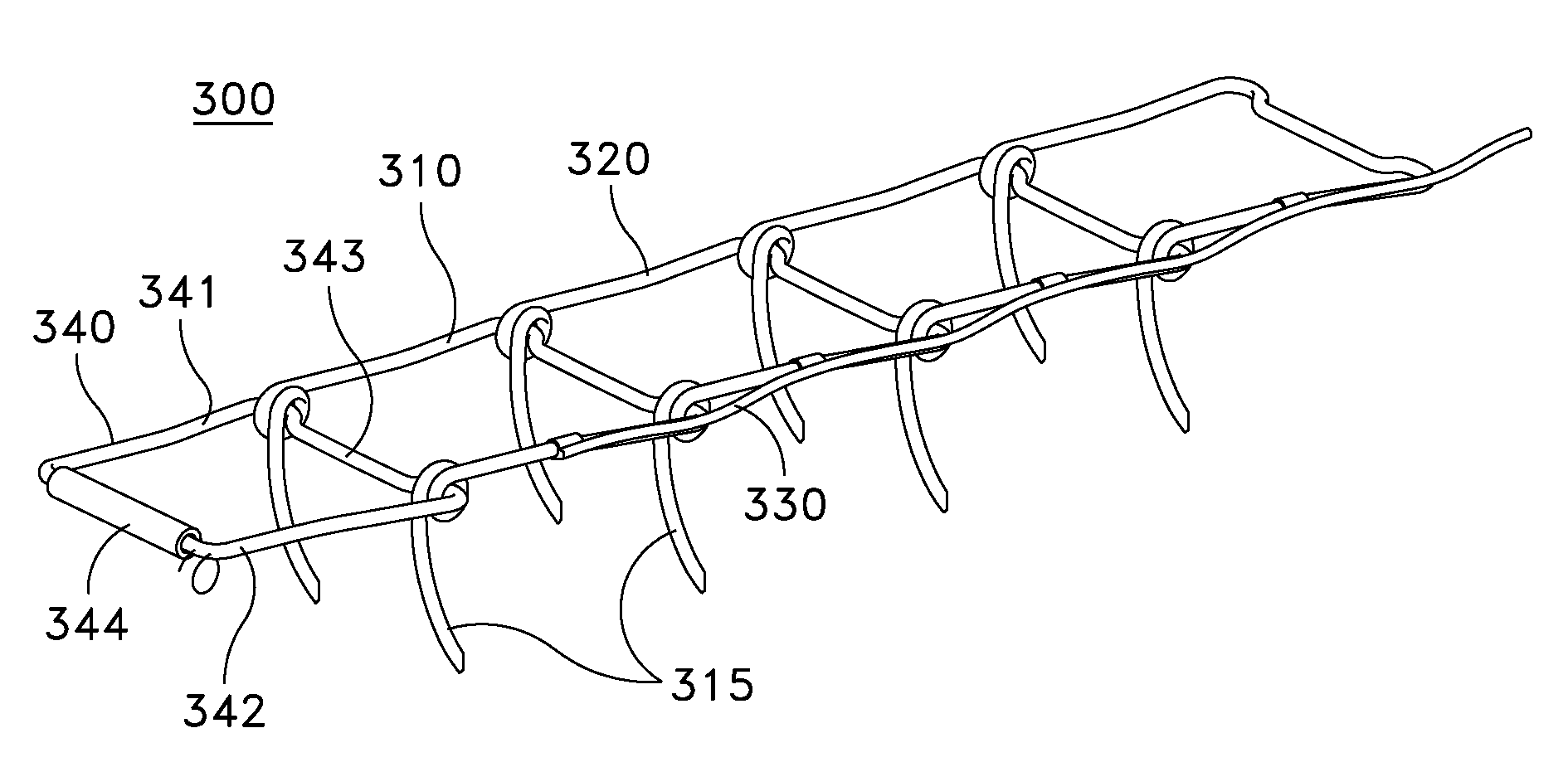
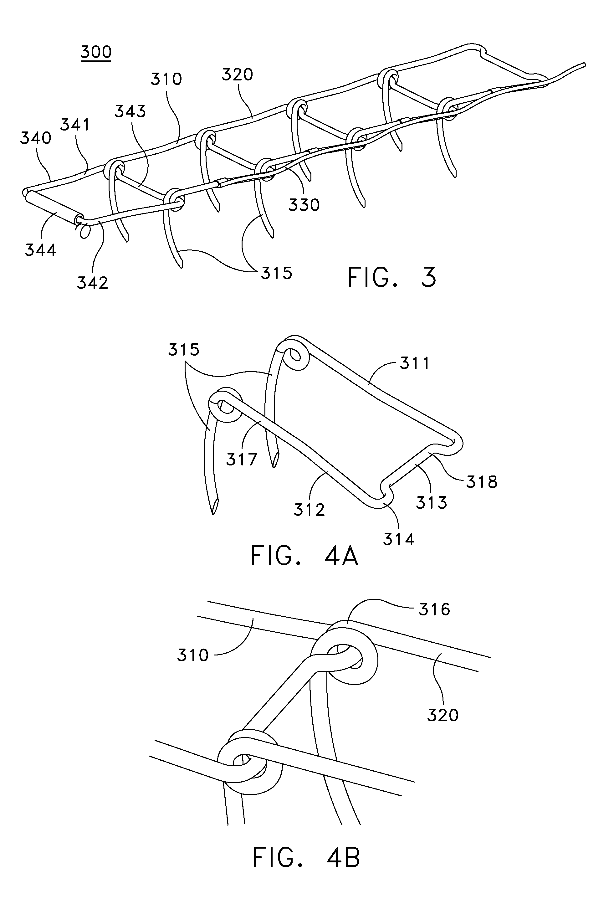
[0016]Referring to FIG. 3, there is shown an electrical ground spike strip 300 in accordance with an embodiment of the invention. The spike strip 300 has two links 310, 320 which are connected directly and rotatably to each other. Each of the links 310, 320 has two spikes 315 each. Dependant upon the final configuration of the spike strip 300, additional links 310 may be adde...


PUM


Abstract

An electrical grounding strip has a first link and a second link, wherein the second link is connected directly to the first link, and each of the first and second links has a portion lying substantially in a plane and has at least one electrically conductive spike attached to the portion. The spike projects generally orthogonally to the plane of the link portion. An electrically conductive ground strap is in electrically conductive contact with the spikes of each of the first and second links.

Description

FIELD OF THE INVENTION[0001]The present invention relates generally to devices for electrical grounding and in particular to devices for electrical grounding for use with mobile electrical equipment.BACKGROUND OF THE INVENTION[0002]Electrical systems such as radar and communication systems require grounding. One known method (shown in FIG. 1) for grounding mobile electrical systems such as radar and communication systems has been to use a single grounding rod 110. The single grounding rod may be, for example, about eight feet long, and is driven into earth. Rod 110 is clamped to cable 112 by clamp 114, and has a connector 116 for being applied to a ground attachment of a device. One shortcoming of this method is that it is very difficult to use for rapidly deploying systems because it requires considerable crew effort and time to install the grounding rod. Another shortcoming is that such a rod is not re-usable because considerable time and energy would be required to completely pul...

Claims


Application Information

Patent Timeline
Patent Type & Authority Patents(United States)
IPC IPC(8): H01R4/66
CPCH01R4/66
Inventor OBLEMAN, JR., MICHAEL R.
Owner LOCKHEED MARTIN CORP
Learn More